
Picking the right manufacturing process for electronic connectors feels like a huge gamble. You know a wrong choice means blown budgets, project delays, and connectors that fail in the field. This decision directly impacts your product’s reliability and your company’s bottom line.
For electronic connectors, choosing between plastic injection molding and metal stamping depends on the component. Use injection molding for high-volume, complex plastic housings, as it offers a very low cost per part. Use metal stamping for producing the simple, durable metal contacts or terminals, as it’s efficient and cost-effective for these high-conductivity parts. The choice balances complexity, material properties, and production volume.
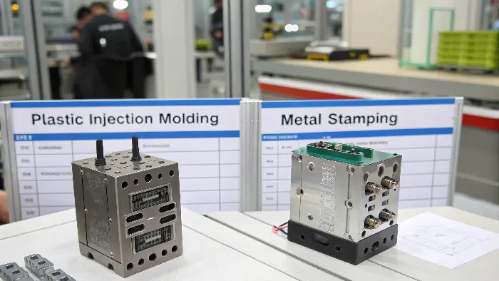
Making the right call between these two methods is critical for project managers. The success of your electronic product often hinges on getting this foundational decision right from the start. I’ve seen projects get stuck because the team chose a process that wasn’t a good fit for their volume or design complexity. Let’s break down the details so you can choose confidently and avoid those common pitfalls. It’s all about matching the process to your specific needs for cost, performance, and scale.
What is the difference between injection molding and stamping?
Are you trying to figure out the core difference between making a plastic part and a metal one for your connectors? It’s a common point of confusion, but getting it wrong can lead to choosing a process that’s completely unsuitable for your part’s function or material.
The main difference is the material and the process. Plastic injection molding injects molten plastic into a 3D mold to create complex shapes, ideal for connector housings. Metal stamping uses a die to cut and form sheet metal into specific shapes, perfect for producing the flat, conductive pins and terminals inside the connector. One builds up a shape from liquid, the other cuts it from a solid sheet.
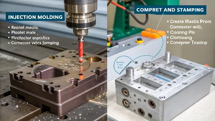
To really understand this, let’s go deeper. Think of it like this: plastic injection molding is like using a high-tech Jell-O mold. We heat up plastic pellets until they become liquid, then inject that liquid under high pressure into a precisely machined steel mold. It fills every tiny detail of the mold cavity. After it cools and solidifies, we eject a finished, complex 3D part. This is why it’s perfect for the intricate outer shells of electronic connectors, which need features like locking tabs, polarizing ribs, and mounting points.
Metal stamping, on the other hand, is more like a very powerful and precise cookie cutter combined with origami. We start with a flat coil of metal sheet. This sheet is fed into a stamping press. The press holds a tool, called a die, that cuts, punches, and bends the metal into the desired shape. This process is incredibly fast and repeatable, making it ideal for producing millions of identical, simple-to-moderately-complex metal components like connector pins, terminals, and shielding. The parts are strong and have excellent electrical conductivity, which is exactly what you need for the "guts" of a connector.
Here’s a simple table to break it down:
| Feature | Plastic Injection Molding | Metal Stamping |
|---|---|---|
| Process | Injects molten plastic into a 3D mold. | Cuts and forms sheet metal with a die. |
| Material | Thermoplastics (ABS, PC, Nylon). | Sheet metals (Copper, Brass, Steel). |
| Part Complexity | Excellent for high complexity, 3D shapes. | Best for low to medium complexity, 2D/2.5D shapes. |
| Best Use Case | Connector housings, insulators, covers. | Connector terminals, pins, shielding. |
| Primary Output | Solid, lightweight, insulating plastic parts. | Strong, durable, conductive metal parts. |
At CavityMold, we live and breathe plastic injection molding. We specialize in creating those complex molds for connector housings. But we always work closely with teams who handle metal stamping for the internal components. A complete connector is almost always a product of both processes working together.
How much does plastic injection molding cost?
You’re looking at your design and thinking, "Okay, this needs to be injection molded, but what’s this actually going to cost me?" It’s the number one question I get. The fear is that the tooling cost will be so high that it makes the project a non-starter, especially if the budget is tight.
Plastic injection molding costs have two main parts: the one-time mold (tooling) cost, which can range from $3,000 to over $100,000, and the per-part cost, which can be mere cents. The high upfront mold cost is spread out over large production volumes, making it extremely cost-effective for mass production. Your final price depends on part complexity, material choice, and total quantity.
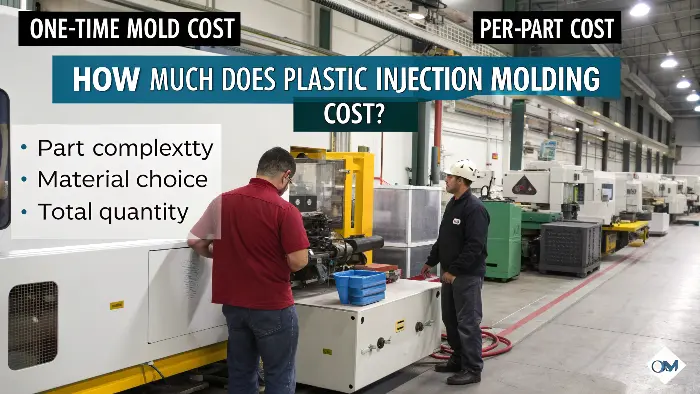
Let’s unpack this because the "it depends" answer isn’t very helpful without context. The cost of a plastic injection molding project is not a single number. It’s an equation with a few key variables.
1. The Mold (Tooling) Cost
This is the big one. It’s the upfront investment to create the high-precision steel mold. This is where most of the initial budget goes. What drives this cost?
- Part Complexity: The more intricate your connector housing is, with undercuts, threads, or fine details, the more complex the mold needs to be. Complex molds with features like side-actions or lifters cost more to design and machine.
- Mold Material: A mold made from softer aluminum is cheaper but wears out faster, suitable for maybe 1,000 to 10,000 parts. A mold made from hardened P20 steel is more expensive but can produce hundreds of thousands of parts. For a high-volume electronic connector, you will almost always need a hardened steel mold.
- Number of Cavities: A mold can have one cavity (making one part per cycle) or multiple cavities (making 2, 4, 8, or more parts per cycle). A multi-cavity mold costs more upfront but dramatically lowers the per-part cost because you’re producing more parts in the same amount of machine time.
2. The Per-Part Cost
This is the ongoing cost you pay for each piece produced. It’s made up of:
- Material Cost: The price of the plastic resin itself. A simple polypropylene (PP) is very cheap. A high-performance engineering plastic like PEEK or Ultem, sometimes needed for connectors in harsh environments, can be very expensive.
- Machine/Labor Cost: The cost to run the injection molding machine, calculated as an hourly rate. The cycle time (how long it takes to inject, cool, and eject one shot) is a huge factor here. Faster cycle times mean a lower cost per part.
The magic of injection molding is how these costs interact. Let’s say a mold costs $10,000. If you only make 1,000 parts, you have to add $10 of mold cost to each part. But if you make 1,000,000 parts, the mold cost per part is only $0.01. This is why it’s the undisputed champion for high-volume production.
What is cheaper than injection molding?
So you see the high upfront cost of an injection mold and get a little nervous. You might be thinking, "My production volume isn’t in the millions yet. Is there a more budget-friendly way to get this done?" This is a key strategic question that can make or break a new product launch.
For lower volumes, metal stamping can be cheaper than injection molding if you’re making a metal part. For plastic parts, CNC machining is often cheaper for prototypes and very small runs (1-200 units) because it requires no tooling. At medium volumes, stamping’s tooling is often less complex and cheaper than injection molding tooling, offering a cost advantage before injection molding’s scale kicks in.
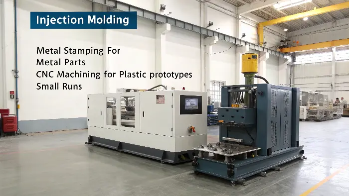
Let’s look at this from the perspective of a project manager like Alex, who needs to justify every dollar. The "cheapest" method depends entirely on what you’re making and how many you need. It’s not a one-size-fits-all answer.
For Low Volume Plastic Parts: CNC Machining
If you only need a handful of your plastic connector housings for prototyping, fit checks, or a very small initial run (say, under 200 pieces), CNC machining is your best friend. It carves your part out of a solid block of plastic.
- Pros: No tooling cost. You can get parts in days. It’s easy to make design changes between parts.
- Cons: The cost per part is very high and doesn’t decrease much with quantity. Some complex internal features possible with molding are difficult or impossible to machine.
- The Tipping Point: As soon as you need a few hundred parts, the total cost of CNC machining will overtake the cost of creating a simple injection mold.
For Metal Parts: Metal Stamping
Now we get back to our core comparison. The tooling for metal stamping, while not cheap, is often less expensive than a complex 3D injection mold. A progressive die for stamping is a marvel of engineering, but it’s fundamentally working in 2.5D. It doesn’t have the complex cooling channels, ejector systems, and 3D cavities of an injection mold.
- Pros: Can be cheaper for medium volumes (thousands to tens of thousands of parts) compared to creating an equivalent part via another process like metal injection molding (MIM). Incredibly fast production speeds mean a very low per-part cost once the tool is made.
- Cons: Limited to sheet metal. Part complexity is lower than what molding can achieve.
The lesson here is to run the numbers for your specific break-even point. We often help clients create an initial "prototype" mold from softer steel or aluminum. It’s a bridge solution—cheaper than a full production mold but capable of producing a few thousand parts to test the market before committing to the six-figure cost of a high-cavitation hardened steel mold.
What are the disadvantages of metal injection molding?
Now, you might hear about another process called Metal Injection Molding, or MIM, and wonder where it fits in. It sounds like the best of both worlds, right? The complexity of injection molding with the strength of metal. But this process has significant drawbacks and is often misunderstood.
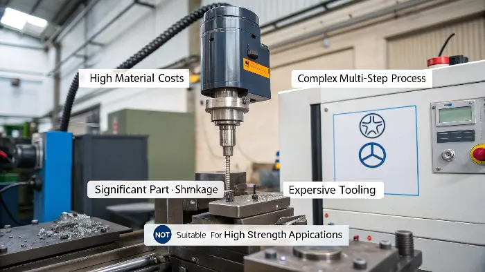
The main disadvantages of Metal Injection Molding (MIM) are high material costs, a complex and lengthy multi-step process (molding, de-binding, sintering), and significant part shrinkage that can affect dimensional accuracy. While it can create complex metal parts, the tooling is expensive, and it is not as strong as wrought or machined metal, making it unsuitable for many high-strength applications.
In my experience, MIM is a fantastic technology for the right application, but it’s a poor choice for most electronic connector components. Let’s dig into why it’s usually not the go-to solution compared to plastic molding for housings and metal stamping for terminals.
First, the process itself is far more complicated than either plastic molding or stamping.
- Feedstock: You don’t start with simple metal. You start with a special feedstock of fine metal powders mixed with a polymer binder. This feedstock is expensive.
- Molding: You inject this feedstock into a mold, much like plastic injection molding. The part that comes out is called a "green" part. It’s fragile.
- De-binding: You then have to remove the polymer binder from the green part. This is usually done with solvents or heat in a carefully controlled process that can take many hours.
- Sintering: Finally, the part (now called a "brown" part) is heated in a furnace to just below its melting point. The metal particles fuse together, and the part shrinks significantly (often 15-20%) to its final, dense state.
This multi-stage process creates several disadvantages:
- Cost: The specialized feedstock and the multiple long steps make the per-part cost relatively high.
- Shrinkage: The significant and not always perfectly uniform shrinkage makes holding very tight tolerances a major challenge. This is a deal-breaker for precision connectors.
- Porosity: The final part is never 100% dense like a machined or stamped part. It has microscopic pores, which can reduce its overall strength and fatigue life.
- Tooling Cost: You still have the high upfront cost of an injection mold, just like with plastic.
So, when would you use MIM? It shines for small, highly complex 3D metal parts that are too intricate to machine economically and impossible to stamp. Think of things like firearm components, medical device parts, or orthodontic brackets. For electronic connectors, however, the components are a perfect match for the combination of plastic molding (housings) and metal stamping (terminals). Stamping gives you strong, 100%-dense, highly conductive terminals from cost-effective sheet metal, and plastic molding gives you complex, insulating housings at a very low per-part cost in high volumes. Trying to use MIM for either of these is usually over-engineering the problem and adding unnecessary cost and complexity.
Conclusion
Choosing between plastic injection molding and metal stamping isn’t about which is better, but which is right for the specific component you’re making. For electronic connectors, the answer is almost always both: injection molding for the complex housing and stamping for the durable metal terminals. Understanding this synergy is key.