
How to Prevent Flow Lines in Injection Molding
Answer in one sentence: Injection molding flow lines usually require coordinated control of part geometry, gate and runner design, venting, melt and mold temperature, injection speed, cooling, and material handling.
Engineering scope: This guide separates design assumptions, process controls, inspection evidence, and buyer decisions so the recommendation can be verified on the actual resin, mold, machine, and production requirement.
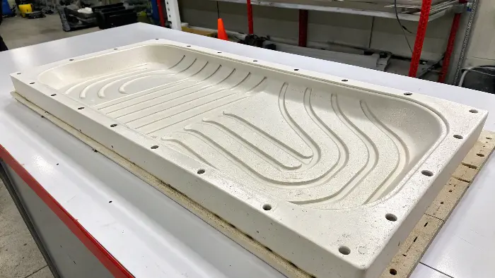
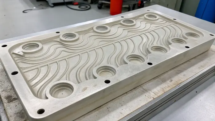
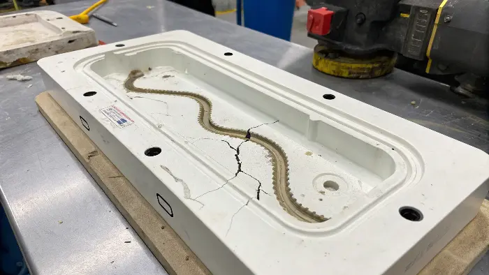
What flow lines are telling you
Flow lines are visible patterns caused by differences in flow-front temperature, velocity, orientation, cooling, or surface replication. They may appear near a gate, around a radius, at a thickness transition, or where the flow hesitates and restarts.
The appearance is not always a purely cosmetic problem. The same flow history can be associated with weld-line strength, orientation, residual stress, gloss variation, or dimensional differences, so the acceptance standard should define both appearance and function.
Review geometry and the feed system first
Check wall transitions, radii, gate location and type, runner size and balance, venting, parting line, and cosmetic zones. A gate that forces a long thin flow path or a sudden thickness change can create hesitation and a visible front. Flow analysis can compare alternatives before steel changes are made.
Process checks that are evidence-based
Verify resin grade, drying, colorant, melt temperature, mold temperature, fill speed, switchover, pack, cooling, and residence time. A temperature or speed change may improve one mark while increasing burn, flash, shear, or warp elsewhere, so inspect the whole part and process window.
Confirm the fix
Retain before-and-after samples, record cavity and lot, measure the critical appearance zone under agreed lighting, and check dimensions and function. Release the change only when the new condition is stable and documented.
Frequently Asked Questions
What causes flow lines near a gate?
Gate geometry, jetting, hesitation, melt temperature, injection speed, wall transition, and local cooling can all contribute. Inspect the gate and flow path before changing settings at random.
Can increasing mold temperature remove flow lines?
It may keep the flow front hotter, but it can also change cycle, shrinkage, flash, and dimensions. Validate the complete part and process window.
Why do flow lines appear only in some cavities?
Cavity balance, gate or vent variation, cooling differences, material distribution, and measurement or lighting conditions can make the pattern cavity-specific.
How should flow-line acceptance be defined?
Specify visual zones, lighting, distance, texture or gloss, allowable patterns, and any associated dimensional or functional limits.
Related Cavity Mold Services
Engineering and DFM; Mold making; Plastic injection molding; Contact Cavity Mold.
For a drawing, resin, tolerance, finish, cavity-count, or process-window review, contact Cavity Mold.