
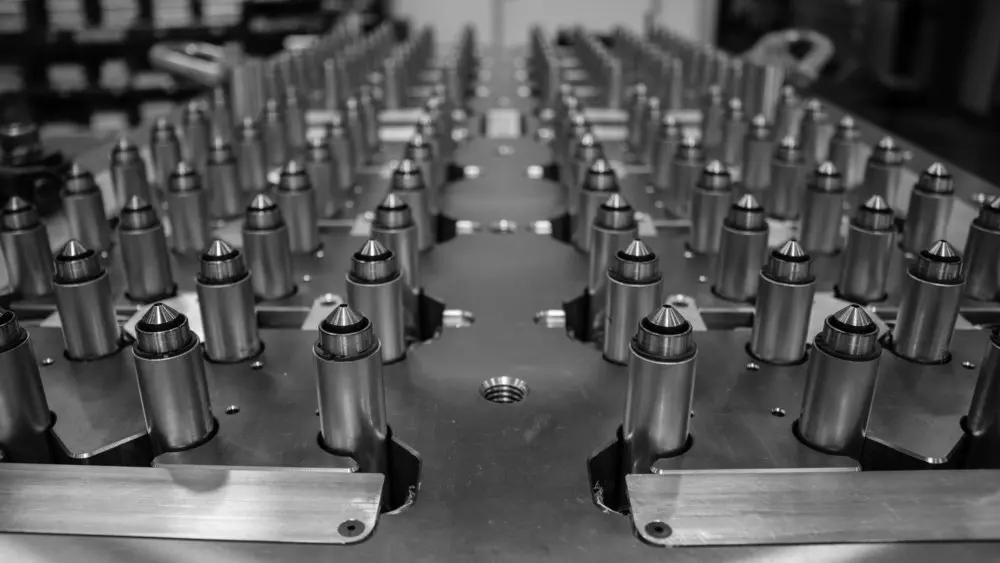
Hot runner injection molding keeps the polymer molten through the sprue, manifold, and gates until it enters the cavity. That can reduce cold-runner scrap and give the mold designer more control over gate placement, but it also adds heated components, start-up procedures, and maintenance responsibilities. The right choice depends on cavity count, material sensitivity, part appearance, expected volume, and the service plan for the tool.

What is a hot runner mold?
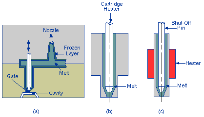
A hot runner is a heated melt-delivery system inside the mold. The manifold distributes polymer to one or more heated nozzles, and the gate controls how the melt enters each cavity. In a cold runner, the runner solidifies with the part and must be separated, reprocessed where the material allows, or discarded. In a hot runner, the runner remains molten between cycles, so the molded part can leave the tool without a conventional runner attached.
The system is not automatically better for every mold. Autodesk describes hot runners as especially useful for multi-cavity production and notes that a combination of hot and cold runners can be the best solution when the part, material, and gate locations require it. See Autodesk’s technical overview of two-plate molds with hot runners when comparing layouts.

Hot runner vs. cold runner: the production decision
| Decision factor | Hot runner | Cold runner |
|---|---|---|
| Material waste | Little or no cold runner scrap in a properly designed system | Runner volume is molded each cycle, although some materials can be reground |
| Tooling investment | Higher because of manifold, nozzles, heaters, thermocouples, and controller | Usually simpler and lower at the start |
| Color or material changes | May take longer because polymer remains in the heated flow path | Runner is removed each cycle, which can simplify purging |
| Gate control | Good flexibility, including valve-gate timing when specified | Gate and runner geometry must be designed around a cooled system |
| Maintenance | Requires electrical, thermal, leak, and nozzle checks | Fewer heated components, but runner and gate wear still matter |
For a high-volume multi-cavity mold, the saved runner material and reduced degating can justify the added capital cost. For a short run, frequent color changes, or a thermally sensitive resin, a cold runner or hybrid system may create a wider and safer operating window.
How hot runner design affects part quality
Gate location and filling balance
Gate positions should be selected with the parting line, cosmetic surfaces, wall thickness, weld-line locations, pressure drop, and packing path in mind. A balanced manifold does not guarantee balanced filling if the cavities have different flow lengths or the part geometry creates different resistance. Flow analysis can compare fill time, pressure, air traps, weld lines, and clamp-force demand before steel is cut. The earlier these decisions are made, the less likely it is that a tool will need gate, manifold, or insert changes after the first trial.
Valve gates and sequential filling
Valve gates can open together or in a timed sequence. Autodesk notes that sequential valve gating can improve balance and flow control and can help position weld lines between gates. It can also increase controller complexity and cost. A buyer should therefore specify whether the requirement is a clean gate vestige, a weld-line location, a low-visibility surface, or simply a stable fill; those are related but different objectives.
Material and process checks
- Confirm the resin’s processing window and residence-time sensitivity from the material supplier’s grade data.
- Specify heater-zone control, thermocouple locations, startup and shutdown procedures, and safe purge material.
- Check gate freeze behavior, shear heating, leakage risk, and whether the system is suitable for filled or abrasive grades.
- Use mold temperature control and cooling that support consistent packing and ejection; a hot runner does not replace a balanced cooling design.
- Record first-shot settings, cavity identification, part-weight trends, and gate appearance at T1 and later production trials.
Common symptoms such as stringing, drooling, splay, burn marks, short shots, or cavity-to-cavity weight variation should be investigated across the gate, melt path, venting, material preparation, and process settings. Changing only injection pressure can hide the cause and narrow the process window.
RFQ checklist for a hot runner mold
- Part material, grade, color, fillers, recycled-content limits, and planned color changes.
- Annual volume, batch size, cavity count, target cycle, and acceptable runner or purge waste.
- Gate type, gate vestige limit, cosmetic surfaces, weld-line restrictions, and shutoff requirements.
- Controller zones, valve-gate strategy, spare parts, leak test, wiring documentation, and maintenance access.
- Trial plan covering cavity balance, part weight, dimensions, appearance, and corrective-action ownership.
For broader mold and flow planning, review Cavity Mold’s engineering service, mold-making process, and the earlier guide to runner design. If you have a CAD model and resin requirement, send the project details through our contact page for an RFQ so the runner choice can be evaluated with the part and production plan.