

Injection molding warpage occurs when different regions of a part shrink or retain stress differently during filling, packing, cooling, and ejection. The result may be bowing, twisting, sink-related distortion, lifted corners, or a part that no longer fits its assembly.

Warpage is not caused by one universal machine setting. Resin structure, fiber orientation, wall thickness, gate location, packing, cooling balance, mold rigidity, ejection, and post-mold conditioning all contribute to the final shape.
Four useful warpage categories
| Variation | What it looks like | Typical investigation |
|---|---|---|
| Regional shrinkage | Gate-side and end-of-fill areas move differently | Packing profile, gate freeze, wall thickness, and flow length |
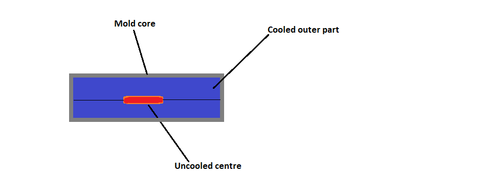
| Through-thickness cooling | One face bows or corners lift | Cavity/core temperatures, cooling balance, and mold contact |
| Orientation shrinkage | Part bends along or across the melt direction | Gate position, flow direction, fibers, and material grade |
| Ejection or post-mold distortion | Shape changes after ejection or conditioning | Part temperature, ejection force, fixture, and conditioning time |
Part-design causes
- Thick sections, bosses, and ribs cool more slowly and may shrink differently from the nominal wall.
- Large flat panels can magnify small temperature or packing differences.
- Sharp corners and abrupt wall changes create stress and uneven flow.
- Glass-filled or fiber-reinforced materials can shrink differently along and across the flow direction.
- Uneven support or asymmetric features can make a small shrinkage difference visible as a twist.
Core out heavy sections, use gradual transitions, and add ribs for stiffness instead of simply increasing wall thickness. The engineering team can review the geometry before tooling.
Process and mold solutions
- Check material lot, drying, melt condition, and grade-specific shrinkage data.
- Map the fill pattern with short shots or simulation and review gate position and balance.
- Run a packing study to establish the shortest stable hold time and pressure.
- Balance cooling circuits, flow rate, inlet temperature, insert cooling, and core/cavity heat removal.
- Check mold deflection, support, ejection, part retention, and the temperature at ejection.
- Measure warpage after a defined conditioning period and at a consistent fixture and temperature.

How to use simulation and trials
A warp analysis can separate differential cooling, shrinkage, and orientation effects. Simulation is directional, not a substitute for material data and trial correlation. Use it to compare gate locations, wall changes, cooling concepts, and packing profiles before modifying steel.
During trials, change one cause family at a time. A higher mold temperature may improve weld-line strength but change cycle and shrinkage. More packing may reduce sink but increase sticking or residual stress. Faster cooling may reduce cycle time but worsen orientation or temperature gradients.
Validation and acceptance
Define the measurement plane, datum, fixture, conditioning time, temperature, and allowed deflection. Measure multiple parts across cavities and cycles. Record whether the part is checked free-state, assembled, or constrained because those conditions can produce different results.
Use the injection molding team to lock a process window and the mold-making team to correct cooling, gate, support, or ejection issues. Contact Cavity Mold with the part drawing and warpage data for a focused review.


Technical references
The Autodesk Moldflow warpage troubleshooting guide explains regional shrinkage, cooling, packing, material, and machine variation. The Autodesk warpage reference connects differential shrinkage and orientation with warpage analysis.