
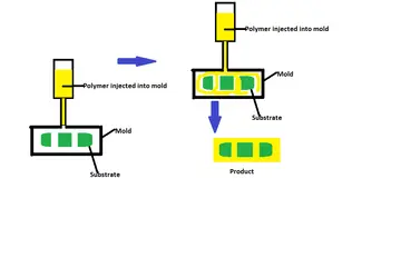
Overmolding injection molding creates one assembly by molding a second material over a rigid substrate, insert, or previously molded component. It can improve grip, sealing, impact protection, appearance, or assembly efficiency, but the part succeeds only when the substrate, overmold material, bond mechanism, gate, vents, shrinkage, and handling sequence are designed together.

What is overmolding?
In a two-step process, the first component is molded or supplied, positioned in a second mold cavity, and then covered with another polymer. The second material may bond chemically to the substrate, lock mechanically around it, or use both mechanisms. Overmolding is different from simply gluing two parts: the mold must locate the substrate and control the second shot without damaging the first component.
Formlabs’ overmolding and insert molding guide distinguishes the two processes and describes how a secondary material is formed over a base component. Use the same distinction in the RFQ so the supplier understands whether the first component is molded in-house, inserted as a purchased part, or produced by another process.

Material compatibility and the bond strategy
| Bond strategy | What controls success | Buyer verification |
|---|---|---|
| Chemical adhesion | Material family, grade, melt temperature, surface condition, and thermal history | Supplier compatibility data plus peel, pull, flex, or environmental testing |
| Mechanical interlock | Holes, ribs, undercuts, wraparound features, and substrate retention | Failure-mode testing that confirms the overmold cannot separate in use |
| Combined bond | Chemical adhesion supported by geometry and controlled processing | Test both the bond and the substrate so the weak link is known |
Do not choose a soft material by hardness alone. Define compression set, tear, abrasion, chemical exposure, temperature, color, feel, and expected flex cycles. A TPE that bonds to one substrate grade may not bond to another grade or surface treatment. Confirm the exact pair with the material supplier and a representative trial.
Substrate and part design
Locate the substrate positively
The substrate should sit against reliable datums and resist movement under injection pressure. Design nests, pins, pockets, or clips around functional surfaces and tolerance stack-up. Keep the overmold away from connector interfaces, threads, sealing faces, and assembly features unless coverage is intentional.
Give the overmold a controlled path
Use consistent overmold thickness where practical, avoid sharp transitions, and provide a flow path that fills without trapping air. Mechanical locks should have enough material around them to avoid tearing. Thin lips and unsupported edges can flash, curl, or deform during ejection.
Gate, vent, cooling, and ejection
Gate location affects weld lines, bond quality, cosmetic appearance, and whether the overmold pushes the substrate out of position. Vents are especially important around the end of fill, deep ribs, and the substrate interface. Cooling must remove heat without creating differential shrinkage that peels or warps the assembly. Ejectors should support the substrate and avoid concentrating force on the soft layer.
For multi-material or multi-shot work, a rotary table, transfer operation, or robot may be used. The best method depends on volume, substrate geometry, cycle balance, labor, and required alignment. Test the complete handling sequence; a strong bond is not useful if the substrate is loaded incorrectly or the part is damaged before inspection.
How to qualify an overmolded part
- Confirm substrate material, dimensions, surface preparation, and cleanliness.
- Run a short process study covering fill, pack, mold temperature, cooling, and transfer or loading time.
- Measure bond strength and failure mode using a product-relevant test.
- Check flash, short shots, air traps, knit lines, surface appearance, dimensions, and assembly function.
- Repeat testing across material lots and the intended process window before production approval.
For related material and process planning, review TPE injection molding, vertical insert molding, and Cavity Mold’s engineering service. Contact Cavity Mold with the substrate drawing, overmold material, bond requirement, annual volume, and inspection criteria.
Build the bond proof around the actual assembly
Qualify overmolding as an assembly, not only as a molded coupon. Define where the second material must stay attached, where it may peel or stretch, and what the finished product experiences during assembly, use, cleaning, temperature change, and chemicals. Chemical adhesion depends on grade pairing and process history; mechanical retention depends on undercuts, holes, ribs, surface condition, and joint stress.
- Record substrate material, revision, surface condition, storage time, and cleaning or preheating.
- Confirm the substrate is located and supported so the second shot cannot move or flash into a functional area.
- Define gate and vent positions to avoid trapped air, jetting, or damaging weld lines.
- Test the finished assembly using the load direction and environment that matter in service.
A flat coupon may not represent a thin rib, sharp corner, texture, or production surface. Include substrate drawing, second-shot grade, hardness, bond/retention requirement, and test method in the RFQ. Use the engineering service before freezing the mold concept.