
Struggling with parts that get stuck, show ugly drag marks, or break during ejection? These issues often stem from poor design for manufacturability, costing time and money. It is frustrating when a good design fails in production because of a few overlooked details.
The key is designing with the manufacturing process in mind: draft angles that let the part release, uniform wall thickness that cools evenly, ribs and bosses sized to avoid sink marks, and a surface finish chosen together with the draft it requires. Get those right and parts eject smoothly, look professional, and are produced efficiently — without costly rework.
For SPI, VDI, and Mold-Tech finish standards, see How Do You Choose the Right Injection Mold Surface Finish?
Why Does Draft Angle Decide Whether a Part Ejects Cleanly?
Draft is a small taper applied to the faces of a part that are parallel to the direction the mold opens. Without it, the part drags against the steel as it is ejected. All thermoplastics shrink as they cool, so a part without draft grips the core tightly; ejection then scrapes the surface, leaves drag marks, and in bad cases bends or breaks the part — or damages the mold.
Protolabs’ published draft guidelines give the working numbers most designers start from: 0.5° on all vertical faces is strongly advised as a minimum, 1° to 2° works well in most situations, and a useful rule of thumb is about 1° of draft per 1 inch (25.4 mm) of cavity depth. Deeper walls need more draft, because the contact area — and the friction and vacuum the part must overcome — grows with depth. A shutoff, where steel slides on steel, needs a minimum of 3°. Parts can be designed with as little as 0.25° to 0.5° where geometry truly allows no more, but that is a compromise to agree with the mold maker before the design is frozen, not a default.
Draft should be designed in from the first prototype, even when the prototype is 3D printed or machined and draft is not yet needed. Adding draft later can change form, fit, and appearance — and a design that works as a print but cannot be molded is a design that has to be redone.
How Much Extra Draft Does Surface Texture Require?
This is where surface finish and design for manufacturability meet. Texture is created by pitting or etching the mold surface, and those microscopic pits are undercuts: without enough draft, the texture locks the part into the mold, and ejection drags the plastic across the texture peaks, leaving shiny streaks and scuffs on what should be a uniform grained surface.
The widely used rule of thumb, from Eastman’s published mold design guide, is to add 1° to 1.5° of draft for every 0.001 in (0.025 mm) of texture depth, on top of the base draft for a smooth wall. Protolabs applies the same principle as fixed minimums: 3° for a light bead-blast finish (PM-T1) and 5° or more for a medium bead-blast finish (PM-T2).
| Surface condition | Texture depth | Draft per side |
|---|---|---|
| Smooth / polished (SPI A–B) | None | 0.5° minimum; 1–2° typical |
| Light matte / fine EDM texture (VDI 18–24) | ~0.001 in (0.025 mm) | 3° minimum |
| Medium bead blast (PM-T2) | ~0.002 in (0.05 mm) | 5° or more |
| Deep chemical grain / leather grain | ~0.0025–0.003 in (0.06–0.08 mm) | 5° or more; check by calculation below |
Worked calculation (illustrative — arithmetic from the rule above, not a measured result): a part with a 0.002 in deep grain starts from a 1° base draft and adds 2 × 1.5° for the texture depth, giving 4° total per side. If the part’s appearance or assembly cannot accept 4°, the finish has to be lightened or the affected faces redesigned — the texture cannot simply be applied to a 1° wall and expected to release.
The practical consequence is that finish selection is a DFM decision, not a cosmetic afterthought. A heavy grain on a tall, straight wall with 1° of draft will produce drag marks on every shot. Decide the finish, check the draft it demands, and confirm both with the mold maker before steel is cut.
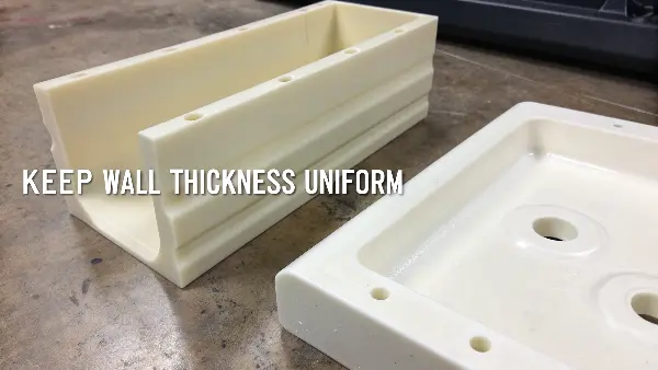
Why Must Wall Thickness Stay Uniform?
Uneven walls cool at different speeds, and different cooling speeds mean different shrinkage — the direct cause of sink marks, voids, and warpage. Protolabs’ wall-thickness guidance states the principle plainly: keep walls uniform, and keep ribs, bosses, and other secondary features at about 40% to 60% of the adjacent wall thickness.
Where a thickness change is unavoidable, taper the transition over a distance of at least three times the thickness difference, rather than stepping from thick to thin. Sharp steps concentrate stress and create a visible sink or flow line on the opposite face. Inside corners need a radius — a common guideline is a fillet radius of about a quarter to half the wall thickness — because a sharp internal corner is both a stress concentration point and a place where the melt struggles to pack.
Recommended nominal wall ranges vary widely by resin, so the resin supplier’s datasheet is the authority for any specific part. As a starting reference, Protolabs publishes these typical ranges:
| Resin | Typical nominal wall range |
|---|---|
| ABS | 0.045–0.140 in (1.1–3.6 mm) |
| PC | 0.040–0.150 in (1.0–3.8 mm) |
| PP | 0.025–0.150 in (0.6–3.8 mm) |
Walls below the recommended range risk short shots and excessive shear; walls above it risk sink marks, voids, and long cycle times. The right wall is the thinnest one that meets the part’s structural and flow requirements — thickness is not strength, geometry is.
How Should Ribs Be Designed?
Ribs add stiffness without thickening the main wall, which is exactly the trade to make: a thin wall plus ribs is stronger and cools more evenly than one thick wall. The rules are simple and widely published:
- Rib thickness: 50–60% of the nominal wall thickness. Protolabs states ribs and gussets should be no more than 60% of nominal wall thickness. A rib as thick as the wall creates a slow-cooling mass at the junction, and the surface opposite the rib sinks as that mass cools.
- Rib height: up to 3× the wall thickness. Taller ribs add little stiffness for the molding difficulty they create.
- Draft on ribs: at least 0.5° per side. Thin, tall ribs are among the hardest features to eject cleanly.
- Fillet at the base: about 0.25× to 0.5× the wall thickness. A radius at the rib-to-wall junction spreads stress and helps the melt pack the corner.
- Gussets for tall ribs. A triangular gusset supports a tall rib far better than making the rib thicker, and it does so without creating a new thick section.
If a rib still shows a sink mark on the visible face, the rib is too thick, the packing is insufficient, or the gate is too far from the junction — in that order of likelihood.
How Do Bosses and Cored-Out Features Work?
A boss — a cylindrical post for a screw or pin — is a thick section by nature, and thick sections sink. The fix is to core the boss out: make it a hollow tube whose wall is 40–60% of the nominal wall thickness, supported by gusset ribs tied back to the nearest wall. A cored boss with gussets is stronger, cools faster, and leaves no sink mark; a solid boss of the same outside diameter does the opposite on all three counts.
The same principle applies everywhere a design accumulates material: coring out removes unneeded mass, leaves only the structure that carries load, and reduces both weight and cooling time. Large flat areas that look like they need thickness usually need ribs instead. Where two walls meet at an angle, avoid a solid triangular mass at the junction — core it, or step the walls so they meet through a radiused transition.
How Does Surface Finish Connect to DFM?
Surface finish is not chosen after the design is finished; it constrains the design. A high-gloss polish (SPI A) needs only the base draft and shows every sink mark, flow line, and ejector-pin witness, so it demands the most uniform walls and the cleanest gating. A matte or grained finish hides minor cosmetic variation but demands the most draft. A finish that changes across the part — gloss on one face, grain on another — needs the draft checked face by face, because the grained faces need more.
That is why the finish standard and the DFM review belong in the same conversation. The finish definitions — SPI grades, VDI grades, and Mold-Tech patterns — are covered in the surface-finish guide linked at the top of this article; the draft, wall, rib, and boss rules above are what make the chosen finish achievable in production.
DFM Checklist: Before You Send the Design for Quotation
| # | Check | Pass rule |
|---|---|---|
| 1 | Draft on all vertical walls | ≥ 0.5° everywhere; 1–2° typical; ~1° per 1 in of depth |
| 2 | Draft on shutoffs | ≥ 3° where steel slides on steel |
| 3 | Draft on textured faces | 3° for light texture; 5°+ for medium/heavy; or base + 1–1.5° per 0.001 in of texture depth |
| 4 | Wall thickness uniform | Nominal wall consistent; transitions tapered over ≥ 3× the thickness change |
| 5 | Wall within resin range | Within the supplier’s recommended range for the chosen resin |
| 6 | Rib thickness | 50–60% of nominal wall; height ≤ 3× wall |
| 7 | Rib and boss draft | ≥ 0.5° per side; gussets on tall ribs |
| 8 | Bosses cored out | Boss wall 40–60% of nominal wall; gusseted to the nearest wall |
| 9 | Inside corners radiused | Fillet radius ~0.25–0.5× wall thickness; no sharp internal corners |
| 10 | Finish and draft agreed | Finish grade specified per face; draft verified against the finish on every face |
| 11 | Ejection considered | Ejector locations away from cosmetic faces; no features that trap the part on the core |
| 12 | Gate and flow reviewed | Gate position supports uniform fill; weld lines kept off cosmetic and structural faces |
Frequently Asked Questions
What is the minimum draft I can use?
0.5° per side on vertical faces is the widely published minimum, and 1–2° works well in most situations. Below 0.5°, discuss feasibility with the mold maker — it depends on the resin, the depth, and the finish.
My part needs a heavy grain but only has 1° of draft. What are my options?
Lighten the finish, increase the draft, or redesign the affected faces so they can carry the draft. There is no process setting that makes a heavily textured, undrafted wall release cleanly.
Why do ribs cause sink marks if they are supposed to prevent them?
Because a rib that is too thick creates a slow-cooling mass at the junction. Keep ribs at 50–60% of the wall thickness and the sink problem largely disappears.
Should I design draft into a 3D-printed prototype?
Yes, if the part will be injection molded later. Draft changes form and fit, and adding it after prototyping means redesigning a part that already works.
Conclusion
Surface finish and design for manufacturability are the same problem viewed from two sides: the finish you want decides the draft you need, and the draft, wall, rib, and boss rules decide whether the part releases cleanly and looks the way it should. Apply the checklist above before the design goes out for quotation — it is far cheaper to add a degree of draft in CAD than to re-cut steel.
If a design needs a DFM review before tooling — draft, wall thickness, rib and boss sizing, or finish selection — contact CavityMold with the 3D model and the finish requirement, and the review can be done before any steel is cut.
References
- Protolabs, "Draft Angle Guidelines for Injection Molding" — https://www.protolabs.com/resources/design-tips/improving-part-moldability-with-draft/ (0.5° minimum; 1–2° typical; ~1° per 1 in of cavity depth; 3° shutoff; 3° light texture PM-T1; 5°+ heavy texture PM-T2)
- Protolabs, "Injection Molding Wall Thickness Guidelines" — https://www.protolabs.com/resources/design-tips/improving-part-design-with-uniform-wall-thickness/ (uniform walls; secondary features 40–60% of adjacent wall; 1° draft per 1 in of cavity depth; ABS/PC/PP wall ranges)
- Protolabs, "Injection Moulded Parts: Adding Strength" — https://www.protolabs.com/en-gb/resources/design-tips/adding-strength-to-injection-moulded-parts/ (ribs and gussets no more than 60% of nominal wall thickness)
- CavityMold, "How Do You Choose the Right Injection Mold Surface Finish?" — https://www.cavitymold.com/how-do-you-choose-the-right-injection-mold-surface-finish/