
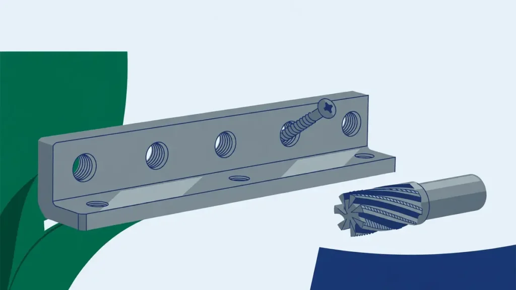
A threaded hole looks simple on a drawing — a diameter, a pitch, a depth — yet it is a common source of rework on machined parts.
Choose the thread method by size, material and depth — cutting tap for small holes in hard materials, forming tap for soft non-ferrous metals, thread mill for larger or adjustable-fit threads, and an insert where the base material is too soft or the joint will be opened repeatedly — then state thread size, pitch, tolerance class, thread depth and drill depth separately on the drawing, and agree how the thread will be gauged before ordering.
How to use this guide: if you are choosing a method, read the first two sections. If the drawing is already made, jump to the callout and checklist sections and check it line by line.
The four ways to put a thread in a machined part
There are two basic types of machined threads: internal threads, cut inside a hole so a screw can fasten directly into the part, and external threads, cut on the outside of a boss or shaft. Most of this guide is about internal threads, because that is what most buyers specify — and where most of the mistakes happen.
| Method | How it works | Best for | Watch out for |
|---|---|---|---|
| Cutting tap | A tap with cutting teeth is threaded into a pre-drilled hole and cuts the thread as it turns. | Small holes (up to about M6) and hard materials; fast, and the usual choice for straightforward tapped holes. | One tap per thread size; chips must escape, so deep blind holes are a breakage risk; a broken tap in a finished part is expensive to remove. |
| Forming tap | A tap without cutting flutes displaces the material to form the thread instead of cutting it. | Soft, non-ferrous metals such as aluminium, brass and copper, and materials that form long ribbons rather than chips. | It distorts the entry hole (and the exit hole on through holes) because of the forces involved; not suitable for hard or brittle materials. |
| Thread mill / single-point tool | A small rotating cutter moves in a circular path around the hole and cuts the thread profile in one or more passes. | Larger holes (above about M6), threads that need an adjustable fit, hard-to-machine materials, and threads to the bottom of a blind hole. | Needs a high-speed spindle and CNC interpolation; slower per hole than tapping on small sizes. |
| Threaded insert | A separate threaded element — a helical coil or a press-fit / key-locking insert — is installed into a plain or tapped hole. | Soft base materials (aluminium, plastics), joints that will be assembled and removed many times, and repair of a stripped hole. | Adds a part, a process step and a cost line; the insert itself must be specified (type, material, installed depth). |
The hardness of the part material, the size of the threaded hole, whether it is blind or through, and the machinery available all affect which method fits. That is the decision to make first, because the method changes the depth the shop can reach, the fit it can hold, and what the drawing must say.
A practical point about CAD: model the pilot hole diameter, not the thread helix. The actual threads should be removed from the CAD model, leaving only the pilot diameter, and the thread itself specified on the 2D drawing. A modeled helix adds nothing the shop can use and can confuse the quoting software — several suppliers’ systems recognise a hole for threading only when it is modelled as a plain pilot hole of the right diameter.
Tapping vs thread milling: which one fits your part?
Tapping and thread milling both make internal threads, but they behave differently, and the difference shows up in the quote and in the failure modes.
| Factor | Tapping | Thread milling |
|---|---|---|
| Speed | Faster per hole, especially on small sizes. High-speed tapping centres can thread holes far more quickly than a thread mill can. | Slower per hole; the cutter must circle the hole. |
| Depth | Can thread deeper holes, including in more rigid materials such as steel. | Depth is limited by the tool: the thread depth generally stays within about 1.5 times the hole diameter to limit deflection, and a supplier’s maximum depth grows with the thread size. |
| Fit control | The fit is fixed by the tap. Tapping does not let the thread fit be adjusted. | The operator can adjust the thread size, much like an end mill, so the fit can be tuned. |
| Tooling | A different tap is needed for each thread size, which consumes tool-magazine positions. | One thread mill can cut many thread sizes that share the same pitch, reducing setup time and tooling. |
| Thread types | One tap, one size, one hand, one profile. | One tool can make internal and external threads, right-hand and left-hand threads, and different profiles. |
| Failure mode | A broken tap in a blind hole can scrap the part; chips packing in the flutes are the usual cause. | Less risk of a broken tool, but needs a high-speed spindle and costs more machine time per hole. |
As a published example of what a supplier’s capability looks like, Protolabs cuts internal threads with a single-lip threading tool rather than a traditional tap, supports metric threads from M2 to M12 and UNC/UNF threads from #2 to 1/2 in., and publishes maximum thread depths from 5.1 mm for its smallest threads up to 25.4 mm for its largest. Those figures are Protolabs’ capability for its own service — not a universal limit and not Cavity Mold’s capability — but they show the shape of the constraint: the deeper the thread, the larger the diameter must be. If your drawing asks for a deep thread in a small diameter, ask the shop whether its tooling can reach it before you release the order.
For a fuller comparison of the two methods, see Xometry’s thread milling vs tapping guide and Protolabs’ threading considerations for CNC machining.
How deep should the thread be?
A thread only holds as far as it engages. The length that matters is the length of thread actually in contact between the bolt and the tapped hole: too little engagement and the internal threads strip under load before the bolt itself fails. The required engagement depends on the strength ratio between the bolt and the tapped material — the weaker the tapped material, the more contact area is needed.
The table below gives the commonly used rules of thumb. They are rules of thumb, not calculated values for your joint: the formal check compares the shear area of the engaged internal threads with the tensile capacity of the bolt, using the actual grades of both. For a critical joint, confirm the depth with the fastener supplier or by calculation; for ordinary joints, the table is where most buyers start.
| Tapped material | Commonly used minimum engagement | Example for an M8 bolt |
|---|---|---|
| Hardened steel | 1.0 × bolt diameter | 8 mm |
| Low-carbon / cold-rolled steel | 1.2 × bolt diameter | about 10 mm |
| Ductile iron | 1.25 × bolt diameter | 10 mm |
| Grey cast iron, brass, copper alloys | 1.5–2.0 × bolt diameter | 12–16 mm |
| Aluminium alloys (6061-T6) | 1.5–2.0 × bolt diameter | 12–16 mm |
| Soft aluminium, zinc die cast | 2.0 × bolt diameter | 16 mm |
| Reinforced plastics / phenolics | 2.5 × bolt diameter | 20 mm |
| Soft plastics (nylon, PVC) | 3.0 × bolt diameter | 24 mm |
Two consequences follow. First, a thread in aluminium or plastic needs roughly twice the engagement of the same thread in steel, which is why a shallow tapped hole in an aluminium housing strips while the identical hole in a steel bracket holds. Second, there are diminishing returns past about 1.5 times the diameter in steel: once the bolt is already strong enough to fail in tension before the threads strip, extra depth adds weight, machining time and tap wear without adding pull-out strength.
And depth is not free: a thread that is deeper than the tooling can reach is not a specification, it is a rework order. Confirm the depth against the shop’s maximum for that thread size before the drawing is released — and if the design needs more engagement than the hole can provide, the answer is usually a larger thread, a longer boss, or an insert, not a deeper callout.
Blind holes vs through holes: what the drawing must say
A blind threaded hole does not go all the way through the part; a through threaded hole has an entry and an exit on opposite faces. Each demands its own drawing treatment, and the blind hole is where most drawing errors live.
Blind holes. A blind hole usually needs to be drilled deeper than the usable thread. The extra depth leaves room for the threading tool to finish its cut and for chips to collect below the threaded section, and the bottom of the hole may end flat (if made with an end mill) or in a cone (if made with a traditional drill). If full threads must extend to the bottom of a blind hole, say so — a bottoming tap is needed, and the shop must know. On the drawing, a blind threaded hole’s notation must state the depths of both the drilled hole and the thread, separately. "M8, 12 deep" on a blind hole is ambiguous: 12 mm of drill, or 12 mm of thread? Write both numbers.
Through holes. The thickness of the part matters, because the tap or thread mill may not be long enough to thread the whole depth from one side. If the tool cannot reach all the way through, the options are to thread as deep as the tool allows and leave part of the hole unthreaded, to thread from both sides (accepting that the threads will not align where they meet, so the two threaded sections must not intersect), or to change the design — a shorter stack, a larger thread, or an insert. Decide this with the shop; do not leave it to be discovered at the machine.
Deep holes. A threaded hole is generally treated as deep when the thread depth is more than 1.5 times the thread diameter. Deep holes create more heat, need more cutting force, and raise the risk of tool breakage, because the tool stays in contact with the part for longer. The usual responses are slower cutting speeds and feeds, a tap with larger flutes so chips clear and coolant reaches the cutting edge, and — where the design allows — a through hole instead of a blind one.
Where threads fail: position, edges and angled surfaces
Most thread failures are not about the thread itself. They are about where the hole sits.
Keep the whole hole inside the part. The outer diameter of the thread is larger than the pilot hole, so a threaded hole placed too close to an edge can break through the side of the part — ruining the surface finish, breaking the tap or the cutting tool, or weakening the part. If extra thickness is needed to hold a threaded hole, add a boss to the part rather than moving the hole to the edge and hoping.
Do not tap on an angle. Machining a threaded hole into an angled surface is difficult: drilling and tapping on a slope loads the tool unevenly, and a traditional tap is likely to break. If the angled surface already exists, machine a pocket first to create a flat surface, then add the threaded hole from that flat. If the angled surface does not exist yet, add the threaded hole first and then machine the angle — taking care that the thread depth still meets the design after the angle is cut.
Mind the finish and the coating. A thread that will be anodised, plated or painted needs the coating stated on the drawing. Plating adds thickness to the thread flanks and changes the fit, and a thread gauged before coating may not gauge the same afterwards. Tell the shop what coating is planned so the tolerance position or the tap size can be set accordingly.
These are the same kind of drawing disciplines as the rest of the part: our CNC machining guide covers the process, materials and inspection framework they sit inside, and our guide to CNC tolerances explains why tightening a tolerance everywhere — including on threads — costs more than tightening it only where fit or function demands it.
Thread class and callout: what to write on the drawing
A thread callout has to answer four questions: what size, what pitch, what fit, and how deep. The syntax is standardised, and using the standard syntax is what lets any shop read the drawing the same way.
Metric threads (ISO). The designation starts with "M", followed by the nominal diameter in millimetres, then the pitch if it is not the standard coarse pitch. The tolerance class follows the pitch, preceded by a dash. Under ISO 965-1, the defaults — what applies when the class is omitted — are coarse pitch, single start, right-hand thread, and class 6g for external threads and 6H for internal threads. Capital letters denote internal threads; lowercase letters denote external threads. So "M8 × 1.25 – 6H" is a complete callout for an internal thread: 8 mm diameter, 1.25 mm coarse pitch, class 6H. Writing "M8" alone leaves the shop to assume the defaults, which is acceptable only if the defaults are what you want.
Unified threads (ASME B1.1). The common general-purpose fit is class 2A for external threads and 2B for internal threads — the pairing most shops expect unless the drawing says otherwise. Tighter classes (3A/3B) exist for closer fits and are harder to make; do not specify them unless the joint needs the tighter fit.
What a complete thread note looks like. For a blind hole: "4× M6 × 1 – 6H, thread depth 10 min, drill depth 14 min, GO/NO-GO gauge". For a through hole: "2× M8 × 1.25 – 6H, through, GO/NO-GO gauge". Every element earns its place: the quantity, the size and pitch, the class, the thread depth, the drill depth where it differs, and the acceptance method. Anything less leaves the shop to assume — and different shops assume differently.
When a threaded insert beats a tapped hole
Sometimes the right answer is not to tap the base material at all, but to install a threaded insert. Three situations point that way:
- The base material is too soft to hold a thread. Aluminium, magnesium and engineering plastics strip far more easily than steel. An insert — a helical coil or a press-fit or key-locking insert — puts a steel thread inside the soft material, so the joint’s strength comes from the insert rather than from the tapped wall.
- The joint will be opened and closed many times. Covers, access panels and serviceable assemblies wear a tapped aluminium or plastic thread out. An insert survives repeated assembly; a tapped hole often does not.
- A tapped hole has already stripped. An insert is the standard repair: drill out the damaged thread, install the insert, and the original fastener size is restored.
The trade-off is real: an insert adds a purchased part, an installation step and a cost line, and the insert itself must be specified — type, material, and installed depth. Some suppliers do not fit coil inserts as standard, so confirm it in the RFQ rather than assuming it. But where the joint matters and the base material is soft, an insert is usually cheaper than the alternative, which is a stripped thread discovered by your customer.
Drawing and RFQ checklist, and how the thread is checked
Use this checklist before the drawing leaves your desk. It is the whole thread specification in one place, and a shop that receives all of it can quote the thread without a round of questions.
| # | Item | What to state |
|---|---|---|
| 1 | Thread size and pitch | Nominal diameter and pitch, e.g. M8 × 1.25, or UNC/UNF size |
| 2 | Tolerance class | 6H/6g for metric (ISO 965-1), 2A/2B for unified (ASME B1.1), or the tighter class if the joint needs it |
| 3 | Thread depth | Usable thread depth, stated separately from drill depth |
| 4 | Drill depth | Full drill depth for blind holes, including the allowance below the thread |
| 5 | Blind or through | Stated explicitly; if through, the part thickness the tool must reach |
| 6 | Method, if it matters | Tapped, thread-milled or insert — state it when the method affects the result; otherwise let the shop choose and state what it chose |
| 7 | Material and coating | Base material grade; plating, anodising or painting if planned, because it changes the fit |
| 8 | Quantity and repeat | Batch size and expected repeat orders — setup and tooling spread differently across one part and one thousand |
| 9 | Acceptance | GO/NO-GO thread gauges, and whether a first-article report is required |
How the thread is checked. The standard acceptance check is a GO/NO-GO thread gauge: the GO gauge must engage fully, and the NO-GO gauge must not engage beyond its limit. That is a functional check — it verifies that a mating fastener will assemble and that the thread is within its tolerance class — and it is far more useful than measuring a single diameter. For the wider acceptance picture, including what a first-article report should contain, see our guide on whether to order a CNC sample before volume production; proving the thread on a sample is the cheapest point to catch a wrong callout, a wrong depth, or a method the shop cannot deliver. For the fullest treatment of threaded-hole design — cutting versus forming, positioning, and deep holes — see Xometry’s threaded holes guide.
Frequently asked questions
Should I model the thread in CAD?
No — model the pilot hole diameter and specify the thread on the 2D drawing. The shop’s quoting and programming software recognises a plain pilot hole; a modelled helix adds no usable information and can prevent the hole from being recognised as a thread feature at all.
How many threads of engagement do I actually need?
Enough that the internal threads are at least as strong in shear as the bolt is in tension. As a rule of thumb, about one bolt diameter of engagement in steel and 1.5 to 2 times the diameter in aluminium, with more in plastics. Beyond about 1.5 diameters in steel there is little extra strength to gain, so extra depth buys mostly machining time.
Can I tap a hole right up to the edge of the part?
Only if the full thread diameter stays inside the part with material to spare. A threaded hole too close to an edge can break through the wall, damage the tool, and weaken the part. Add a boss or move the hole; do not rely on the shop to notice.
What if my part needs a thread the shop cannot make?
Ask before the order, not after the first parts arrive. Maximum thread depth grows with thread diameter, and small diameters cannot be threaded deeply — as one published example, a supplier’s smallest threads may be limited to about 5 mm of depth while its largest reach about 25 mm. If the design needs more, the options are a larger thread, a boss, threading from both sides, or an insert.
Send the drawing and your thread requirements
If your machined part needs threaded holes, send the CAD and the 2D drawing with the thread callouts — size, pitch, class, thread depth and drill depth — the base material, whether the joint will be assembled repeatedly, quantities, delivery region and timing. Contact Cavity Mold with the part files, and the machining review can confirm the thread method, depth and gauging before the order is quoted.