
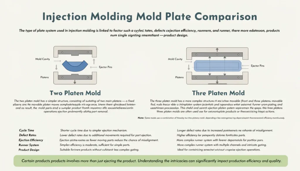
You’re probably also wondering which is better for your needs. In this article we shall discuss both types;, highlight the key features of both and make comparisons between them. We’ll explore what type of products and injection molding processes each type is suited for and the requirements. This will help you in deciding which is best suited for your intended product.
As we will come to understand by the end of the article, the type of plate used is linked to factors like cycle time, defect rates, ejection efficiency, runner system and others1. A single more significant determinant of the type of plate system used is the product design2. This is in fact the first thing that influences the choice of plate. Certain products will only be possible with a three platen mold. It is important to be able to recognize this in the early stage of product design.
For many, understanding of the injection molding process is limited to “the mold opens and the product gets ejected from the mold”. However, the mold opening process has a lot more to it. So here we explain that in more detail.
In order to understand these two types of plates, the article first gives a brief overview of injection molding. From here we then focus on the role and function of the plate as well as the mechanisms. The rest of the article then goes into details about each type of plate in separate headings followed by comparison between the two.
Overview of Injection Molding Process
The Two Plate Mold
A two plate mold system comprises more than just two plates that open and close as many basic injection molding diagrams and simulations imply. Rather, the two plate injection mold comprises a number of parts that come together to make the 2 plate mechanism work. These are:
- The clamping unit plate
This comprises the cavity plate and the core plate. These are also referred to as the stationary part and the moving part - Mold Cavity and mold core
These parts form the final shape of the product. This is where the polymer melt fills. It is contained within the plates. - Sprue brush
This is the part connecting the nozzle of the injection unit to the clamping unit. It forms the path through which the molten plastic flows into the mold cavity. It is typically located within the stationary part of the plate. - The Runner System
This exists where more than one cavity is used. This is the pathway for the molten plastic to flow from the injection unit, via the sprue into the clamping unit, to get to the mold cavities. - The Gates
Before the molten plastic can get into the mold cavity, it passes through a gate. This controls the flow rate and flow pattern into the mold cavity where the product finally forms. The gate can be of different types such as valve gate, pin gate, tunnel gates, and diaphragm gate amongst others. The type of gate and the location of the gate depends on factors like the wall thickness, geometry of product, rheology of the polymer melt and other factors. - Guide Pins and Bushes
These are connecting pins and bushes that support proper alignment of the mold parts as the mold closes. This ensures the part is well formed, no leakage occurs and no defects associated with improper mold closing and alignment that may lead to the part being damaged or cause inefficiencies in the process. - Ejection System
The molding process is very crucial to the injection molding process occurring efficiently. It is important that the part gets ejected smoothly without getting stuck. A stuck part means the next process cannot smoothly transition into the next cycle and that delay adds to production time. The more seamless the ejection process, the more time gets saved. This system comprises ejector pins connected to ejection mechanisms that pushes the product out, aiding the demolding process after part is formed and cooled. This is a crucial part of mold design. - Cooling system
This is a heat exchange system integrated within the mold to take heat away from the product and into a heat sink like water or other cooling fluid. This can either be straight channels or more complex channels strategically located around the mold. The cooling fluid flows through these channels to allow indirect contact between the molten plastic and the cooling fluid in order to remove heat in a controlled manner. The cooling rate and uniformity of cooling are important factors to consider in designing cooling systems as these can significantly impact cycle time and occurrence of issues such as warpage, shrinkage and others. - Back Plate
This is a fixture that provides additional structural support to the mold and plates. Although not directly involved in the molding process, it is important for strength and keeping all the parts in place particularly under high clamping forces. - Locating Ring
This part is used to align the injection molding system with the clamping unit. Under the rigorous shear pressure in the mixing and melting stage and a reciprocating screw, there is tendency for movement of parts. Efficient injection and mold filling is supported by proper alignment of the injection unit and the clamping unit. .The locating ring serves this purpose. - Vents
These are small gaps that allow gaseous compounds to exit the system. These can be trapped air or volatiles formed during the heating of the polymer. Gases in the polymer melt can cause all sorts of problems such as burn marks and internal voids that lead to damaged product and even equipment parts. Vents are placed in strategic positions to aid removal of gases from the process.
Mechanism of the Two Plate Mold System
The Mechanism of the two plate mold system is as follows:
After the accumulation chamber is filled and the reciprocating screw reaches the limit switch, the mold closing mechanism is activated, the screw then serves the role of injecting polymer melt into the closed mold. The melt passes through the nozzle, into the sprue, through the runners and via the gate, into the mold cavity. The melt fills the mold cavity, the part gets cooled by the cooling system. Once the cooling time has elapsed, the mold opens into two halves and the demoulding mechanism is activated and the part is ejected. Thus ends the cycle and begins a new cycle. A separate stage for separating the runners from the part should take minimal time and effort and may or may not include regrind and recycle depending on the standard requirements.
The Three Plate Mold
The overall injection molding process remains the same for both two plate and three plate mold systems. The difference is in the way in which the mold opens and closes and how the product gets ejected. The three plate mold system comprises of:
- The Stationary plate
- The floating plate
- The moving plate
Therefore the key difference between the two plate mold and the three plate mold in terms of parts is the floating plate which is often also referred to as the centre plate. The three plate mold has two parting lines instead of one and the mold opening and closing mechanism is more complicated. It consequently adds to the cycle time. Although using sophisticated and highly efficient automated systems can bring this down to microseconds, still opening and closing of the plate mold generally takes longer than two plate molds.
In additional to the components present in the two plate mold, a three plate mold system also requires additional parts which are
- sprue puller
- Additional ejection system for the runners
- Runner Strippers
The functions of these parts are described within the description of the mechanism of the 3 part mold opening below.
Mechanism of Three Plate Mold
The three plate mold opening and closing mechanism is such that clearance is provided for the product to be ejected, typically due to complexity of the design. The separation of the different parts of the plates occurs such that the mold filling occurs through a path that allows for the formation of the complex part, while also making it possible to eject the part through mold opening and ejection mechanism with ease.
In many cases the sprue and runners are ejected separately from the main part. The first stage of the mold opening mechanism ejects the sprues and runners (if cold runner system), while the second stage of the opening mechanism ejects the main part. To achieve this the floating plate gets pulled away from the fixed plate. The runner remains on the fixed plate on the feed side by the runner puller.
The next stage involves ejecting the runners with the aid of the runner stripper plate and the sprues through the action of the sprue puller. In the third stage, the molded part gets ejected. This is achieved by the separation of the mold core and mold cavity which has been assisted by the parting of the floating plate. The ejection system aids in the demoulding of the part.
Although described in three separate stages. After the first stage, the remaining mechanisms typically occur simultaneously. Therefore the first stage; that is clearing away the runner, is crucial to the product ejection. The complexity of this stage, other than the product design, is also dependent on whether a hot or cold runner system is being used.
A hot runner system simplifies this initial clearance process as it eliminates the need for stripping off the runner after every cycle. This contributes towards reducing cycle time. Although it might not necessarily mean reduced complexity.
This short simulation further provides a visual explanation of the 3 part mold mechanism.
Choosing the right Mold for your Process
The two plate mold system has only one parting line. The product will typically come out with the runner and sometimes sprues attached. These contribute to scrap and you need to have a fast seamless process for detaching these. Nonetheless the two plate mold system is generally simpler and costs less. This is in part due to less complicated design requirements and less complex mechanisms.
Choose two Plate Mold if:
- You have a simple design and want to minimize cost
- Its fine for the product to be ejected with the runner attached to the product
Choose Three Plate Mold If:
- You require a separate conveyor belt to collect sprues and runner parts and another to collect the main molded part
- You have a complex design that cannot be achieved through simple two plate mold opening and closing mechanism
Conclusion
The 2 plate mold system is generally a simpler system for injection molding. However more complex product design may necessitate 3 plate molds. Products designed with undercuts, complex geometry or specific requirements benefit from the advantages 3 part molds provide. Simple 2 part mold systems where the mould and runners can be ejected together are more common for everyday low cost products. Therefore to answer the question posed at the start of the article, the main difference lies in the mechanism of mold opening and part ejection and the choice of which to use depends on your product design. Your mold maker will communicate which best suits your need, nonetheless this article provides the fundamental understanding of both.
By Ololade Olatunji
7 August, 2026
"Comparison Of Two And Three Plate Molds Plastic Injection Molding For …", https://www.academia.edu/38427204/Comparison_Of_Two_And_Three_Plate_Molds_Plastic_Injection_Molding_For_Mold_Design_Selection_24_pages. Research on injection molding design indicates that platen configuration affects multiple process parameters including cycle efficiency and part ejection characteristics, though the magnitude of these effects depends on specific mold geometry and part design. Evidence role: general_support; source type: research. Supports: that mold platen configuration influences manufacturing parameters such as cycle time and ejection performance. Scope note: Support may be contextual, as the relationship between platen type and these specific outcomes varies with part complexity and mold design. ↩
"[PDF] Injection Mold Design", https://people.tamu.edu/~hsieh/ICIA/Richland-Injection-Molding-Web/Richland-Part-4-Mold-Design.pdf. Injection molding engineering literature identifies part geometry, undercut features, and ejection requirements as key factors in determining appropriate platen configurations, alongside considerations of production volume and cost. Evidence role: general_support; source type: education. Supports: that part geometry and design features are primary considerations in mold platen system selection. Scope note: While product design is consistently cited as important, sources may not explicitly rank it above all other selection criteria. ↩