Designing plastic parts for injection molding can feel like navigating a minefield. A small oversight in your design can lead to expensive mold modifications, production delays, and a lot of frustration. You worry about every detail, knowing that one mistake could derail your entire project timeline and budget, putting you under immense pressure.
The best way to design plastic molded parts is to follow a two-stage process. First, focus on the part design itself, ensuring it adheres to Design for Manufacturability (DFM) principles like uniform wall thickness, draft angles, and proper rib design. Second, you or your partner must design the injection mold, which involves creating the core and cavity, feed system, cooling channels, and ejection mechanism to produce that part efficiently.
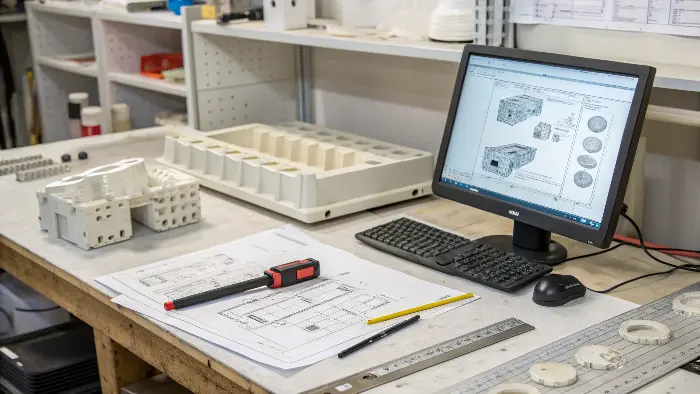
It sounds straightforward on the surface, but the real challenge is in the details. I remember a project early in my career where a client insisted on sharp internal corners for aesthetic reasons. We knew this would create stress points, but we moved forward. The first batch of parts cracked during assembly, costing weeks of delays and a complete mold rework. To avoid that kind of headache, you need to understand the entire process. Let’s break it down step-by-step, starting with the fundamentals.
What is plastic mould design?
You often hear the term "mold design," but what does it actually involve? For many project managers, it can seem like a mysterious process that happens behind closed doors. This lack of clarity makes it difficult to communicate your needs to your manufacturing partner, which can lead to misunderstandings and results that don’t meet your expectations. Let’s pull back the curtain and define it clearly.
Plastic mold design is the specialized engineering process of creating the tool, or mold, used in injection molding. It involves designing the mold’s core and cavity, which form the part’s shape. It also includes engineering the runner system to deliver plastic, gates for entry into the cavity, cooling channels to solidify the part, and an ejection system to safely remove it. It is the complete manufacturing blueprint for your part.
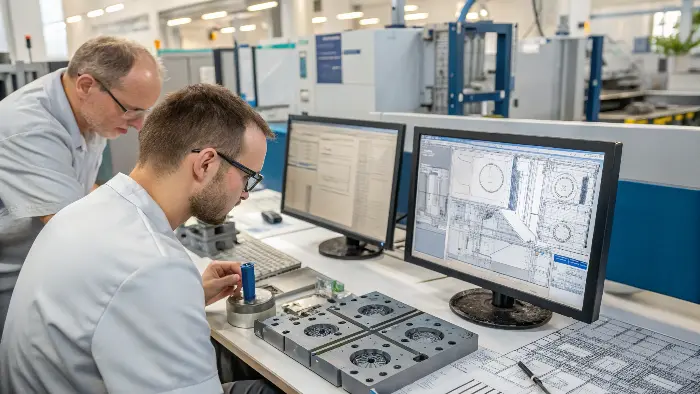
To truly understand mold design, you have to look at its core components and how they work together. It’s much more than just a block of steel with a hole in it. Think of it as a complex machine where every part has a critical job.
The Core and Cavity: The Heart of the Mold
The core and cavity are the two halves of the mold that come together to form the shape of your part. The cavity is the female side, typically forming the exterior, cosmetic surface of the component. The core is the male side, which forms the interior features. When the mold closes, the space between the core and cavity becomes the part. The precision of these two components directly determines the accuracy and surface finish of your final product.
Supporting Systems for Production
Beyond the core and cavity, several other systems are essential for the mold to function correctly. A great mold design is one where all these systems are balanced to create a robust and efficient process.
| System | Purpose | Why It’s Critical |
|---|---|---|
| Feed System | Delivers molten plastic from the machine to the cavity. | Affects fill time, pressure requirements, and overall part quality. |
| Cooling System | Circulates fluid to cool and solidify the part quickly. | Controls the cycle time and prevents defects like warping. |
| Ejection System | Pushes the finished part out of the mold. | Prevents damage to the part during removal from the core. |
| Venting System | Allows trapped air to escape the cavity as plastic flows in. | Prevents defects like short shots, burn marks, and voids. |
At CavityMold, we’ve spent over a decade perfecting this balance. A successful mold isn’t just about making a part; it’s about making a part perfectly, thousands of times over.
How do you design a plastic part for molding?
You have a brilliant concept for a new product. But turning that digital idea into a physical plastic part that can be mass-produced is a huge hurdle. You’re worried that your design won’t be manufacturable, leading to endless back-and-forth with your supplier, skyrocketing tooling costs, and frustrating delays that push back your launch date. By following a few key principles, you can design parts that are functional, cost-effective, and optimized for injection molding from day one.
To design a plastic part for molding, you must focus on Design for Manufacturability (DFM). This means incorporating features like a consistent wall thickness to prevent sink marks and warping. You must also add draft angles, typically 1-2 degrees, to all vertical faces for easy ejection from the mold. Finally, you need to carefully design features like ribs for strength and bosses for assembly, while avoiding complex undercuts where possible.
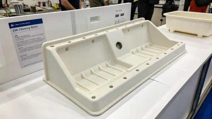
When we receive a new part design, these DFM principles are the first things we look for. They tell us immediately whether the part is ready for toolmaking or if it needs refinement. Let’s dive into the most important rules you should follow.
The Golden Rule: Uniform Wall Thickness
This is the single most important rule in plastic part design. When molten plastic cools, it shrinks. If one area of your part is much thicker than another, the thick section will cool slower and shrink more, pulling on the adjacent thin section. This causes ugly defects like sink marks, voids, and internal stresses that can lead to warping or part failure. By keeping your wall thickness as uniform as possible, you ensure the part cools evenly, resulting in a stable, strong, and cosmetically clean product.
Essential Design Features for Molding
Beyond wall thickness, several other features are critical for a successful molded part. Getting these right during the design phase will save you an enormous amount of time and money.
| Feature | Best Practice | Reason |
|---|---|---|
| Draft Angle | Add 1-2 degrees on all walls parallel to the mold opening. | Allows the part to release from the mold without drag marks or damage. |
| Ribs | Design them to be 50-60% of the main wall thickness. | Adds strength and stiffness without creating thick sections that cause sink. |
| Bosses | Core them out and connect them with ribs, not in corners. | Provides strong mounting points for screws without causing sink marks. |
| Fillets/Radii | Add generous radii to all inside and outside corners. | Reduces stress concentrations and helps the molten plastic flow smoothly. |
I remember a client, a project manager like Alex, who sent us a design for a housing with sharp internal corners. Our mold flow analysis immediately flagged those corners as high-stress areas. We showed him how the part would likely crack under normal use. By simply adding a 2mm radius to those corners, we eliminated the risk before we even ordered the steel for the mold. That’s the power of good DFM.
How do you make a plastic part design moldable?
Your part design looks perfect in your CAD software, but your manufacturing partner comes back and says it’s not "moldable." What does that even mean? This kind of feedback can be incredibly frustrating. It feels like a major setback, forcing you back to the drawing board without a clear understanding of what needs to change. Making a part moldable is all about bridging the gap between your design intent and the physical realities of the injection molding process.
To make a plastic part design moldable, you must first select the right material for its geometry and application. Then, you must analyze your design for undercuts, which are features that prevent the part from being ejected directly from the mold. Simplify or eliminate these where possible. Finally, you must strategically plan the gate location and parting line to ensure the part fills correctly and cosmetic surfaces are preserved.
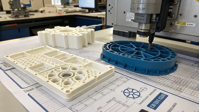
Making a part moldable is a collaborative effort between the designer and the mold maker. It involves making smart choices about materials and geometry long before the mold design even begins.
Material Selection is Key
The plastic resin you choose has a massive impact on moldability. Different materials behave differently when melted. Some, like ABS, have high flow rates and can easily fill thin, complex sections. Others, like glass-filled polycarbonate, are much stiffer and require more pressure and larger gates to fill the mold properly. The material’s shrinkage rate is also critical. We have to design the mold cavity to be slightly larger than the final part to account for this shrinkage. If you choose a material that is not suited for your part’s geometry, no amount of mold design magic can fix it.
Tackling Undercuts and Complex Geometry
An undercut is any feature on a part that would get stuck in the mold if it opened in a simple in-and-out motion. Think of a snap-fit clip on the side of a housing. To create this feature, the mold needs a special mechanism, like a side-action or lifter, that moves into place to form the shape and then moves out of the way before the part is ejected. These mechanisms add significant cost, complexity, and potential failure points to a mold. Sometimes, a clever redesign can eliminate an undercut entirely. For example, adding a small slot or "pass-through" below a clip can allow the main core to form the feature, removing the need for a side-action.
Planning the Gate and Parting Line
The parting line is where the two halves of the mold meet. This line will often leave a faint witness mark on the final part. The gate is the small opening where molten plastic enters the cavity, and it will also leave a small mark (a vestige) after it’s trimmed. The location of these features is a critical decision. We always work with our clients to place the parting line and gate in non-critical, non-cosmetic areas. This planning ensures the part not only functions correctly but also meets its aesthetic requirements.
How do you design the actual injection mold?
The part design is finalized, DFM has been applied, and the material is selected. Now comes the most critical and expensive phase: designing the actual injection mold. The pressure is on because any mistake made in the mold design is incredibly difficult and costly to fix once steel has been cut. It can jeopardize the entire project budget and timeline. A systematic mold design process, combining advanced software with decades of hands-on experience, is the only way to guarantee a successful tool.
Designing an injection mold begins with the final 3D part data. We first establish the parting line and apply a specific shrinkage factor based on the chosen plastic. Then, we design the core and cavity blocks. After that, we engineer the feed system (sprue, runners, gates), the cooling channels for thermal management, and the ejection system (pins, sleeves) to safely remove the part. The entire assembly is then validated using mold flow analysis software.
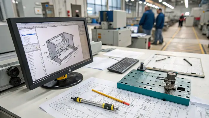
This is where our expertise at CavityMold truly shines. We transform a client’s part design into a robust, high-performance manufacturing tool. Here’s a look at how we approach this complex process.
From Part to Mold: The First Steps
Once we receive your final CAD file, our work begins. The very first step is to apply a shrinkage factor. Every plastic shrinks as it cools, so we must make the mold cavity slightly larger than the desired final part. A material like ABS might shrink 0.5%, while Nylon could shrink up to 2%. Getting this wrong means the final parts will be out of tolerance. Next, we determine the optimal parting line. This decision impacts the mold’s complexity, cost, and the final appearance of the part. We analyze the geometry to find a parting line that simplifies the tool and keeps any witness marks in inconspicuous areas.
Engineering the Mold’s Systems
With the foundation set, we design the intricate systems that make the mold function. This is a multi-stage process where each system must work in harmony with the others.
| Design Stage | Key Activity | Our Focus at CavityMold |
|---|---|---|
| 1. Core/Cavity | Create the main forming surfaces based on the scaled part data. | We use high-precision CNC machining to achieve exact dimensions and the specified surface finish. |
| 2. Feed System | Design the runners and gates that deliver plastic to the cavity. | We use mold flow analysis to optimize for balanced filling and minimal material waste. |
| 3. Cooling | Lay out a network of cooling channels within the mold blocks. | We ensure uniform cooling across the part to minimize cycle time and prevent warping. |
| 4. Ejection | Strategically place ejector pins, sleeves, or plates. | We position pins on strong, non-cosmetic areas to push the part out without leaving marks. |
We use advanced mold flow simulation software to create a digital twin of the molding process. This allows us to predict exactly how the plastic will fill the cavity, identifying potential issues like air traps, weld lines, or sink marks. We can then fix these problems in the digital design phase, saving our clients the enormous cost and delay of fixing a physical steel tool. It’s all about being proactive, not reactive.
Conclusion
Designing plastic molded parts is a collaborative dance between part design and mold design. By focusing on manufacturability from the very beginning—with uniform walls, draft angles, and smart material choices—you set the stage for a smooth and successful project. A well-engineered mold then brings that vision to life reliably and efficiently. Master these principles, and you’ll master your molding projects.
