
Key takeaway: There is no universally better process than injection molding; the right choice depends on volume, geometry, material, finish, tolerance, tooling, and development stage.
Start with the part and the business case
Injection molding can be a strong choice for repeatable thermoplastic parts once geometry, material, volume, finish, tolerance, and tooling investment align. It is not automatically the best choice for every prototype, low-volume part, geometry, or material.
Define annual and batch volume, development stage, material and performance, dimensions and tolerances, surface finish, lead time, tooling budget, change frequency, and the cost of scrap or failure before comparing processes.
Engineering perspective: Cavity Mold reports more than 15 years of mold-making experience. In a DFM review, the team considers part geometry, resin and grade, expected volume, critical tolerances, surface finish, tooling, and trial evidence together. This is an early process screen; final suitability depends on the actual part and validation requirements. Learn about Cavity Mold’s mold-making work.
Where alternatives may fit
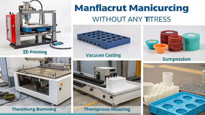
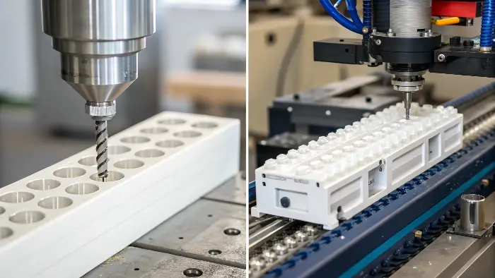
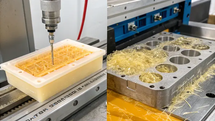
3D printing can support fast design iterations or complex low-volume parts; CNC can suit certain materials, tolerances, or low volumes; thermoforming can fit sheet-based large parts; compression or injection-compression may suit specific materials or precision needs. For certain plastic and composite applications, CNC router machines can provide flexible machining for prototypes and low-volume parts. Each option has its own constraints, finishing, and inspection requirements.
Compare the complete workflow, including tooling, fixtures, programming, post-processing, assembly, inspection, lead time, repeatability, and scale-up. A process that is fast for one prototype may be inefficient for a long production run, while tooling may be justified when demand and stability are clear.
Choose the process that fits the decision stage
There may be a better process than injection molding for a specific part or stage, but “better” depends on volume, geometry, material, tolerance, surface, tooling investment, speed to learn, and production economics.
| Process | When it may fit | What to verify before committing |
|---|---|---|
| 3D printing | Early design learning, complex geometry, or low quantities when the selected process and material meet the need. | Prototype fit does not prove molded behavior; confirm material performance, surface, tolerances, post-processing, and test requirements. |
| CNC machining | Functional prototypes or low-volume parts when available stock material and tool access fit the design. | Include setup, fixturing, tool reach, cycle time, material waste, finishing, and inspection. |
| Thermoforming | Sheet-based parts or large surfaces when the geometry suits forming. | Review draw depth, wall-thickness distribution, trimming, finish, material limits, and assembly. |
| Compression molding | Parts and materials suited to a compression-molding charge or a different tooling approach. | Confirm material, press and tool design, flash and trimming needs, inserts, and inspection criteria. |
| Injection-compression molding | Precision applications where the material, geometry, and process requirements support this route. | Confirm process-specific tool and press needs; use analysis and trials to validate the part requirements. |
| Blow or rotational molding | Hollow or large parts with a matching process window. | Check part geometry, wall distribution, material, tooling, and downstream finishing. |
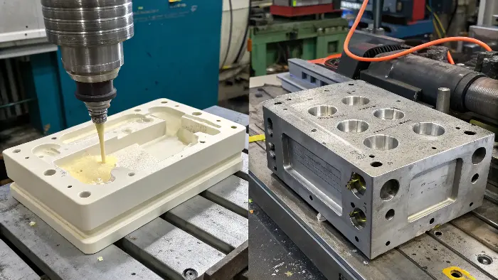
| Injection molding | Repeatable plastic parts when design stability, features, finish, and production economics justify tooling. | Include tool investment, DFM, cycle, maintenance, material, inspection, and the cost of later changes. |
Decision inputs
- Expected volume by month and total demand uncertainty.
- Material, wall, geometry, tolerance, finish, assembly, and functional requirements.
- Iteration speed, tooling budget, supply risk, and inspection evidence.
- What must be learned now versus what must be optimized for production.
Use engineering to compare routes against the part and send the chosen assumptions through the RFQ route.
Use a staged decision
Many programs use additive or machined prototypes to learn, then move to bridge or production molding after the design stabilizes. Revisit the decision when volume, geometry, material, performance, or schedule changes; the ‘better’ process can change with the program stage.
A practical selection sequence
- Define demand: estimate batch quantity, annual volume, expected program life, and forecast uncertainty.
- Record requirements: specify the resin or grade, function, geometry, critical dimensions and tolerances, surface finish, assembly, and operating conditions.
- Compare equivalent scopes: ask suppliers to quote the same quantity and delivery scope, and separate engineering, tooling or fixtures, part price, secondary operations, inspection, and packaging.
- Validate the chosen route: agree what a prototype, bridge tool, or production trial must prove. Check representative parts against the actual fit, function, appearance, and quality criteria.
- Revisit when assumptions change: volume, design stability, material, schedule, or quality requirements can change which process makes sense.
Compare total program cost, not only part price
Use the same production horizon and quality scope for every quote. A useful comparison is:
Expected program cost = one-time engineering, tooling, and fixtures + (manufacturing, finishing, inspection, and packaging per part × expected quantity) + expected change and scrap costs.
Tooling can raise upfront cost while lowering repeat-part cost, but the result depends on the design, tool life, material, cycle, demand, and how often the design may change. Ask suppliers to state the assumptions behind both the one-time and per-part figures.
Frequently Asked Questions
Is injection molding always the lowest-cost process?
No. It can require substantial upfront tooling and design work. Total cost depends on volume, geometry, material, cycle, tooling, quality, finishing, and the development stage.
When can 3D printing be a better option?
It may fit rapid iterations, complex low-volume geometry, or situations where avoiding tooling matters, provided material, surface, tolerance, and functional requirements are acceptable.
How should processes be compared?
Compare volume, geometry, material, finish, tolerance, tooling, lead time, post-processing, inspection, risk, and the cost of changing the design—not only piece price.
What production volume makes injection molding cheaper?
There is no universal cutoff. Compare tooling and engineering against per-part costs over the expected program volume, using the same material, tolerances, finish, inspection, and delivery assumptions. Part size and complexity, tool life, cycle time, scrap, and design changes can shift the break-even point.
Can a 3D-printed or CNC-machined prototype qualify the injection-molded part?
It can validate selected geometry or functions, but it does not by itself establish the molded material’s behavior, shrinkage or warpage, surface finish, or production repeatability. Define validation around the intended production material and process.
What information should I provide for a process review?
Share the current CAD model or drawing, material and grade, batch and annual quantities, critical tolerances, finish, function, target timing, and inspection or quality criteria. These inputs make supplier recommendations and quotes easier to compare.
Related Cavity Mold Services
Engineering and DFM; Mold making; Plastic injection molding; Contact Cavity Mold.
Have a drawing, resin, finish, volume, or quality requirement to review? Contact Cavity Mold for a project discussion.