

Draft angle is the intentional taper that lets a molded wall move away from the tool surface during mold opening and ejection. It reduces sliding, scuffing, sticking, ejection force, and the risk of damaging a cosmetic surface or the mold.
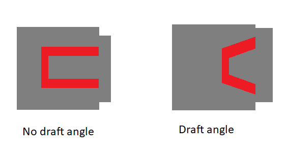
There is no single draft angle that fits every part. A shallow polished wall, a deep textured wall, a high-shrinkage resin, and a shutoff surface have different release requirements. Draft should be reviewed in the CAD model before tooling, not added after the first failed trial.
Why draft is needed
As a thermoplastic cools, it often shrinks toward the core. A wall with zero draft can press against the mold surface over its full depth. Texture creates microscopic undercuts that increase resistance. A deep wall magnifies the effect, and an ejector system may then push locally hard enough to create whitening, distortion, scratches, or visible pin marks.
Draft also gives the cutter and polisher access to the wall. On a deep narrow feature, inadequate draft can complicate machining, venting, polishing, texture release, and inspection even when the part appears possible in a CAD model.
A practical draft-angle framework
| Design condition | Starting direction | What must be confirmed |
|---|---|---|
| Shallow polished or lightly finished wall | Use positive draft and keep it consistent | Resin shrinkage, wall depth, polish direction, and ejection force |
| Deep wall or narrow cavity | Increase draft as depth and contact area increase | Core retention, vacuum, cooling, and ejector layout |
| Textured or etched surface | More draft than a polished wall is commonly needed | Texture depth, texture direction, and texture supplier guidance |
| Shutoff or metal-to-metal seal | Use draft in the slide or shutoff travel direction | Steel-safe adjustment, flash risk, and wear |
Published rules of thumb are useful for early design, but they are not acceptance criteria. The final value should be agreed with the toolmaker after the resin, wall depth, finish, and ejection strategy are known.
External, internal, and feature-specific draft
- External walls: normally draft away from the parting line so the part releases with the cavity or core movement.
- Internal walls: draft toward the open space and check that ribs, bosses, and core pins do not create a larger interference.
- Ribs and bosses: use draft on both sides where possible and core thick features to limit sink.
- Text and logos: choose raised or recessed text with the pull direction, tooling access, and cosmetic requirement in mind.
- Snap-fits and hooks: do not hide an undercut inside a nominally drafted wall; it may require a slide, lifter, or a design change.
Draft, texture, and ejection
Surface finish changes friction and the size of microscopic features that the part must clear. A polished wall may release with less draft than a textured wall of the same depth. However, increasing draft can change appearance, mating dimensions, or the usable envelope of the part. If appearance or fit limits draft, discuss alternatives such as a parting-line change, a replaceable insert, a different texture, an ejection-side change, or a controlled lifter.
How to check draft in a DFM review
- Set the primary mold opening direction and identify the intended A-side and B-side surfaces.
- Run a color-coded draft analysis from the real pull direction, including slides and lifters.
- Mark zero-draft, reverse-draft, texture, shutoff, and deep-wall areas.
- Compare draft with wall thickness, shrinkage, ejection pins, cooling, and cosmetic zones.
- Record exceptions and obtain written approval when a critical feature intentionally has limited draft.
The [engineering team](/engineering/) can review the part before the [mold-making process](/mold-making/) begins. This is usually less expensive than modifying steel after T1.
RFQ information to provide
Provide the CAD model, resin grade, surface-finish specification, texture reference, critical mating dimensions, ejection-side preference, annual volume, and any no-draft exceptions. Ask for a draft report with the proposed parting line and actions. [Contact Cavity Mold](/contact/) if you want a manufacturability review before releasing the tool.
Technical reference
The Protolabs draft-angle guide explains why material, shrinkage, depth, texture, and ejection must be evaluated together rather than reduced to one universal number.