
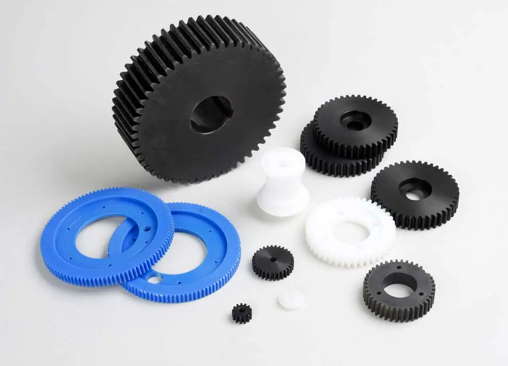
Plastic gear injection molding can produce repeatable teeth and integrated hubs at production volume, but gear performance depends on material behavior, shrinkage, mold accuracy, gate position, cooling, and inspection—not on tooth geometry alone. Define the load, speed, temperature, humidity, lubrication, life, noise, backlash, and mating gear before choosing the resin or mold.

Material selection for plastic gears
Common candidates include acetal, nylon, reinforced nylon, PBT, and other engineering grades. The right choice depends on tooth stress, wear, friction, temperature, moisture, chemical exposure, dimensional stability, and whether the gear runs against plastic or metal. Filled grades can increase stiffness and wear resistance but may introduce fiber orientation and directional shrinkage.
AGMA’s AGMA 920-B15 information sheet for plastic gears relates candidate material properties to plastic gear operating conditions and molding shrinkage. It also makes clear that application testing and supplier data are needed for a specific gear.
Gear design and mold accuracy
Tooth geometry and load sharing
Use a gear designer or validated calculation method to define module or diametral pitch, pressure angle, face width, root fillet, backlash, and contact ratio. Plastic gears can be optimized for the material and application, but a direct metal-to-plastic substitution without checking tooth stress, creep, wear, and temperature is risky.
Hub, bore, and alignment
The hub and bore control runout and shaft fit. Keep the hub transition smooth, support the core, and avoid a gate or ejector arrangement that distorts the bore. Concentricity, flatness, and axial location can matter as much as individual tooth dimensions.

Gate, flow, cooling, and ejection
Gate position affects fiber or molecular orientation, weld lines, tooth-to-tooth variation, and radial shrinkage. A center gate can support symmetry in some spur gears, while another design may require a different approach because of the hub, insert, or machine. The decision should be validated with flow and shrinkage analysis or a structured trial.
Cooling must be balanced around the gear rim and hub. Uneven cooling can create runout, ovality, tooth-profile variation, or backlash drift. Ejector pins should not damage tooth flanks; sleeve or stripper ejection may be preferred depending on the mold design and part geometry.

Gear inspection and production validation
| Feature | What to verify |
|---|---|
| Teeth | Profile, pitch, runout, tooth thickness, burrs, and surface damage |
| Bore and hub | Diameter, concentricity, fit, perpendicularity, and insert position if applicable |
| Assembly | Backlash, center distance, noise, torque, and engagement with the mating gear |
| Life | Wear, creep, temperature, humidity, load cycle, and lubricant compatibility |
Measure gears in a controlled condition and distinguish mold capability from material conditioning. Part weight, cavity identification, mold temperature, and process settings should be recorded so a later change can be traced to the gear data.
For gear tooling and production, review Cavity Mold’s engineering service, mold-making capability, and injection molding service. Contact the team with the gear drawing, load case, mating gear, resin candidate, and test plan.
Use a functional gear validation worksheet
Gear acceptance should connect molded geometry to operating condition. Record torque, speed, duty cycle, temperature, humidity, lubricant, mating gear, expected life, noise target, backlash, and measurement method. A gear can meet a tooth dimension and still fail because of deflection, shrinkage, eccentricity, flash, moisture, or material change under load.
| Control area | Inspect or test |
|---|---|
| Geometry | Tooth form, pitch, runout, concentricity, face width, and flash. |
| Material state | Grade, reinforcement, moisture or conditioning, color, and lot. |
| Function | Backlash, torque, noise, wear, temperature rise, and life. |
| Tool/process | Gate, cooling, ejection, cavity wear, and process records. |
Design teeth, hubs, and bores with the selected material’s shrinkage and orientation in mind. Send mating gear data, load case, life requirement, resin, and critical inspection characteristics through the engineering page.