
Injection Molding Weld Lines: Causes, Prevention, and Design Fixes
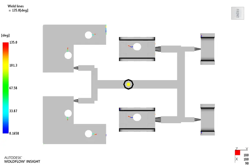
Injection molding weld lines, also called knit or meld lines, form when two or more melt fronts meet after flowing around a hole, insert, rib, or other obstacle. The line may be only cosmetic, or it may reduce strength if the fronts arrive too cold, contaminated, or poorly aligned. The most reliable solution is to manage the flow path during part and mold design; machine settings are used to refine the result after the design risks are understood.
What is a weld line?
A weld line is the visible or structural boundary where separate flow fronts recombine. A meld line is often used for a more favorable meeting condition, but shop language commonly calls both conditions weld lines. The line location depends on gate position, wall thickness, holes, inserts, runner balance, melt temperature, mold temperature, injection speed, and venting.
Why do weld lines matter?
They can appear as a color change, notch, gloss variation, or weak region. The risk is highest where the line crosses a load-bearing feature, sealing surface, thin section, or visible exterior. A line on a noncritical interior surface may be acceptable if the drawing and functional requirements allow it.
Weld-line acceptance
Identify whether the meeting point is cosmetic or functional, then agree on the inspection or test before releasing the mold.
How do you prevent or reduce weld lines?
1. Change the flow path first
Review the gate location and number of gates. Moving a gate can move the weld line away from a functional or cosmetic area, but it may create a new line elsewhere or change the packing balance. A wall-thickness transition, flow leader, or local geometry change may also redirect the flow front. Use a filling study when the part has multiple gates, holes, inserts, or long flow lengths.
2. Improve the meeting condition
Within the resin supplier’s processing window, a higher melt or mold temperature and an appropriate injection speed can help the fronts meet with more heat and pressure. The change must be checked for degradation, flash, shear, cycle time, and dimensional stability. Increasing speed is not a universal fix: a faster front can worsen air traps or jetting if the gate and venting are not suitable.
3. Vent the last-to-fill area
Air must leave the cavity as the melt arrives. Poor venting can cool the front, create burn marks, and increase the pressure needed to fill the area. Inspect vents for depth, land length, blockage, and connection to the outside of the mold. Venting details must follow the resin, tool steel, surface requirements, and the mold maker’s approved design.
4. Check material and process stability
Confirm the exact resin grade, filler content, colorant, drying requirement, melt temperature, mold temperature, fill profile, and change-over point. A weld line that changes from shot to shot may indicate process variation rather than a single gate problem.
| Observation | Likely direction for investigation |
|---|---|
| Line always appears at the same hole or insert | Gate location, flow path, part geometry, and local venting |
| Line is visible and part is weak | Meeting temperature, pressure, speed, resin grade, and fiber orientation |
| Line appears with burn or short shot | Air evacuation, vent blockage, and end-of-fill speed |
| Line moves between cavities | Runner balance, cavity temperature, and process repeatability |
Autodesk’s weld and meld line guidance recommends considering gate position, part thickness, melt and mold temperature, ram speed, and runner design together. BASF’s injection molding troubleshooter is also useful for separating weld-line symptoms from other defects.
What should the DFM review record?
- Expected weld-line locations and whether each is cosmetic, functional, or unacceptable.
- Gate and runner options considered, with the trade-off for each.
- Vent locations and access for cleaning.
- Material grade and process assumptions used for the analysis or trial.
- The inspection method for appearance and strength-related requirements.
For design support, connect the weld-line review to DFM engineering, mold making, and production molding. Send the CAD file and drawing for a practical review before the gate and parting line are finalized.