
Struggling to get your plastic part designs right for manufacturing? The transition from a CAD model to a physical product is often filled with costly errors and delays. A solid understanding of mold design is the key to avoiding these pitfalls and ensuring a smooth production run.
Mastering injection mold design involves understanding key part design principles like uniform wall thickness, draft angles, and material choice. You also need to know the core components of the mold itself, such as the core and cavity, sprue, runners, and gates. Proper planning in these areas ensures high-quality parts and efficient manufacturing.
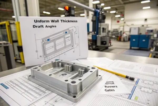
I’ve seen countless projects get derailed by simple design oversights. It’s a common story. But it doesn’t have to be yours. Understanding the fundamentals is your best defense against production headaches. Let’s start at the very beginning, with the most important decision you’ll make.
What factors should you consider before choosing injection molding for a part?
You have a great part design, but is injection molding the right process? Choosing the wrong manufacturing method can lead to blown budgets and missed deadlines. You need a clear framework to make the right call for your project’s specific needs.
Before choosing injection molding, consider your production volume, part complexity, material requirements, and budget. Injection molding is ideal for high-volume production due to high initial tooling costs but low per-part costs. It excels with complex geometries but requires careful design for manufacturability. Material choice and tolerance requirements also heavily influence this decision.
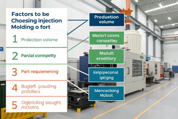
Making the right choice upfront saves a massive amount of time and money. I always walk my clients through a structured decision process. We look at the project from several angles to see if injection molding is truly the best fit.
Production Volume and Cost Analysis
The first question is always about quantity. Injection molding involves a high initial investment in the mold, which can cost thousands or even tens of thousands of dollars. However, the cost per part becomes extremely low once the mold is made. This makes it perfect for mass production. I remember a client who wanted to mold just 500 units. After we ran the numbers, it was clear that CNC machining was more cost-effective for that small batch. As a rule of thumb, if you’re planning to produce over 10,000 units, injection molding is usually the most economical choice.
Part Geometry and Complexity
Next, we look at the part’s design. Injection molding is fantastic for creating complex and intricate shapes. You can incorporate ribs, bosses, and snaps directly into the part, reducing the need for secondary assembly. But this complexity comes with rules. You have to design the part so it can be easily ejected from the mold. This means considering things like draft angles and avoiding undercuts. If a part is very simple, like a flat plate, other methods might be cheaper, even at high volumes.
Material and Performance Requirements
What does your part need to do? Injection molding supports a massive range of thermoplastic polymers, each with unique properties. You can choose materials that are flexible, rigid, heat-resistant, or chemical-resistant. For a project requiring a specific high-performance polymer for a consumer electronics housing, injection molding was the only viable option. We needed the material’s specific flame-retardant properties and a smooth surface finish, which molding delivers perfectly. You need to ensure the material you need can be injection molded effectively.
How do you design a part for injection molding?
You’ve decided injection molding is the right path. Now what? Simply handing over a standard 3D model to a molder will almost certainly lead to problems. You need to optimize your design specifically for the injection molding process to ensure success.
To design for injection molding, you must incorporate key principles into your part’s geometry. This includes maintaining a uniform wall thickness to prevent warping, adding draft angles for easy ejection, radiusing corners to reduce stress, and carefully planning the placement of features like ribs and bosses to support the structure without causing defects.
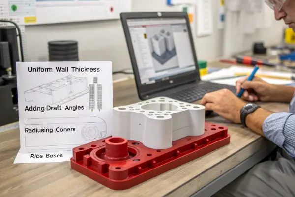
This is where my experience as an engineer really comes into play. Design for Manufacturability (DFM) isn’t just a buzzword; it’s a critical step that separates successful projects from failed ones. Let’s break down the core principles I focus on with every design.
Maintain Uniform Wall Thickness
This is the golden rule of injection molding. When molten plastic cools, it shrinks. If one part of your wall is thick and another is thin, they will cool and shrink at different rates. This creates internal stress, leading to warping, twisting, and sink marks on the surface. I always aim for the thinnest possible wall that still meets the part’s structural needs. If you need extra strength, it’s better to add ribs rather than making the whole wall thicker. On a recent project for an enclosure, we reduced the wall thickness from 3mm to 2mm and added a strategic rib pattern. This not only fixed the sink mark issue but also reduced the cycle time and material cost.
Add Draft Angles
Imagine trying to pull a perfect cylinder out of a tight-fitting cup. It creates a vacuum and friction makes it stick. The same thing happens in a mold. A draft angle is a small taper, typically 1 to 2 degrees, applied to the faces of the part that are parallel to the direction the mold opens. This tiny angle prevents the part from scraping against the mold wall during ejection. It reduces friction, prevents scratches, and lowers cycle times. Parts without draft are one of the most common and easily avoidable defects I see.
Radius Corners and Edges
Sharp internal corners are stress concentrators. When plastic flows into a sharp corner, it can become turbulent and not fill properly. As the part cools, stress builds up in these corners, making them weak points that are prone to cracking. By adding a generous radius (fillet) to all inside and outside corners, you allow the plastic to flow smoothly and distribute stress evenly. A good rule of thumb is to make the inside radius at least 0.5 times the wall thickness. This simple change dramatically improves the strength and durability of the finished part.
What are the key design considerations for the injection mold itself?
Designing the part is only half the battle. The mold is a complex piece of machinery, and its design directly impacts part quality, cycle time, and cost. Getting the mold design right is crucial for a smooth production run.
Three key design considerations for the mold are the gating system, the cooling system, and the ejection system. The gate location and type determine how plastic fills the cavity. The cooling channels’ design controls cycle time and part quality. The ejection system ensures the finished part is removed without damage.
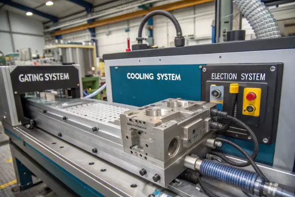
When I review a mold design, I spend most of my time focusing on these three areas. A mistake in any one of them can turn a great part design into a pile of scrap. Here’s a closer look at why each one is so important.
The Gating System: Your Part’s Entry Point
The gate is the opening where molten plastic enters the part cavity. Its size and location are critical. A poorly placed gate can cause cosmetic defects like flow lines or structural issues like weld lines, where two plastic fronts meet. The type of gate also matters. For example, a "hot runner" system keeps the plastic molten all the way to the gate, which eliminates runner scrap and can reduce cycle times, but it adds to the mold’s complexity and cost. I once worked on a part with a large, flat surface that required a perfect finish. We used a "fan gate" to spread the plastic flow evenly and avoid any blemishes on the critical surface.
The Cooling System: Managing Heat and Time
Cooling accounts for the majority of the injection molding cycle time. An efficient cooling system is essential for profitability and part quality. The goal is to cool the part evenly and quickly. We design cooling channels that run through the mold, circulating water or oil to draw heat away. If one area cools slower than another, you’ll get warping and sink marks. We use mold flow simulation software to analyze the heat distribution and optimize the placement of these channels. It’s a bit like designing the circulatory system for the mold; it needs to reach everywhere effectively.
The Ejection System: Getting the Part Out Safely
Once the part is cooled and solid, it needs to be pushed out of the mold. This is done by the ejection system, typically a series of ejector pins. The placement and size of these pins must be carefully considered. If you push on a weak area, you could break or deform the part. The pins will also leave small, circular marks on the part’s surface. We always try to place these marks on a non-cosmetic or hidden surface. For a clear plastic lens project, we had to use a special "stripper plate" ejection system to avoid leaving any marks on the optical surfaces.
| System | Primary Function | Key Design Choices | Impact on Part |
|---|---|---|---|
| Gating System | Fills the mold cavity with plastic | Gate type, size, and location | Affects cosmetic appearance and structural integrity (weld lines). |
| Cooling System | Removes heat from the plastic | Channel layout, diameter, and coolant flow | Controls cycle time, prevents warping, and reduces sink marks. |
| Ejection System | Pushes the finished part out | Ejector pin size, location, and type | Prevents part damage and determines cosmetic marks. |
What are the main components of an injection molding machine?
To truly understand mold design, you have to understand the machine it works in. An injection molding machine is a powerful and precise piece of equipment. Knowing its main parts helps you appreciate how the mold, material, and machine all work together.
An injection molding machine has two main units: the injection unit and the clamping unit. The injection unit melts and injects the plastic into the mold. The clamping unit holds the mold shut during injection and opens it to eject the part. These two units work in harmony to automate the molding cycle.
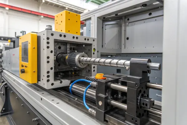
I’ve spent a lot of time on factory floors, standing next to these machines. Watching them run is impressive. It’s a precise, powerful, and repetitive dance of mechanical and hydraulic systems. Let’s walk through the key components and what they do.
The Injection Unit
This is the part of the machine responsible for preparing and injecting the plastic. It’s made up of a few key components.
- Hopper: This is where the raw plastic pellets are loaded into the machine. It’s like a big funnel that feeds the barrel.
- Barrel and Screw: The barrel is a heated cylinder, and inside it is a reciprocating screw. As the screw rotates, it pulls pellets from the hopper, and the combination of heat from the barrel and friction from the screw’s rotation melts the plastic. The screw also acts as a plunger. When enough plastic is melted, the screw pushes forward, injecting the molten plastic into the mold with high pressure.
Think of it like a giant hot glue gun. The screw’s job is to melt the plastic "glue" and then force it out the nozzle when it’s time to inject.
The Clamping Unit
This unit is all about force. Its job is to hold the two halves of the mold together against the immense pressure of the injected plastic. If it doesn’t hold tight, plastic will leak out, creating "flash" on the part.
- Platens: There are two main platens: a stationary platen where the front half of the mold is mounted, and a moving platen where the back half is mounted.
- Clamping Mechanism: A powerful hydraulic or all-electric system moves the moving platen to open and close the mold. It also provides the tonnage, or clamping force, to keep the mold shut. Machines are rated by this tonnage, from small 20-ton machines to massive 4000-ton ones. Selecting a machine with the right clamping force is crucial; too little and the mold flashes, too much and you can damage the mold.
The clamping unit is the muscle of the operation, ensuring the mold can contain the injection pressure and then open reliably to release the final product.
Conclusion
Mastering injection mold design starts with understanding the core decisions: whether to mold, how to design the part, and how to design the mold itself. By focusing on these fundamentals, from wall thickness to cooling channels, you can ensure your project runs smoothly, on time, and on budget.