
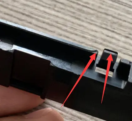
Injection molding flash is a thin, unwanted fin of plastic that escapes at a parting line, slide, insert, vent, ejector, or another clearance in the mold. Flash is not caused by one setting alone. Diagnose it by locating the flash, checking mold fit and support, and then reviewing clamping force, filling pressure, temperature, speed, venting, and shot size.

Where does flash appear?
- Parting line: the cavity and core are not sealing under the molding load, or the surface is worn, damaged, dirty, or deflected.
- Slide, lifter, or insert: a shutoff has insufficient contact, poor support, wear, mismatch, or foreign material.
- Vent or ejector: the clearance is too deep, the vent is damaged, the ejector is loose, or the steel cannot support the pressure.
- Gate or thin edge: local overpacking, excessive pressure, a gate that freezes late, or an edge that is too flexible.
What causes injection molding flash?
| Possible cause | What to inspect | Why it matters |
|---|---|---|
| Mold mismatch or damage | Parting surface, shutoffs, inserts, guide system, and contamination | A gap lets melt escape even with reasonable process settings |
| Insufficient or uneven clamping | Projected area, clamp setting, platen parallelism, and mold support | Melt pressure can separate a weak or unsupported area |
| Excessive fill or pack pressure | Change-over, shot size, hold profile, and cavity pressure | More pressure increases the force acting on the mold interface |
| High melt or mold temperature | Actual temperature, thermocouple location, and residence time | Lower viscosity makes it easier for melt to enter a clearance |
| Fast fill at the end of the cavity | Velocity profile, end-of-fill pressure, and venting | High local pressure can open or damage a weak vent |
How should flash be diagnosed?
- Map the flash on a sample and compare it with the parting line, vents, ejectors, slides, and inserts.
- Clean the mold and inspect the affected steel before changing the process.
- Confirm the mold closes fully at operating temperature and that support pillars, guide pins, and platens are aligned.
- Check shot size, change-over point, hold pressure, melt temperature, mold temperature, and injection speed against the approved window.
- Make one controlled change at a time and measure flash height, part weight, dimensions, and appearance.
How can flash be prevented?
Correct the tool condition
Remove foreign material, repair damaged shutoffs, restore the parting surface, support thin plates, and replace worn components when the clearance is the root cause. Do not repeatedly increase clamp force to hide a damaged mold; excessive force can accelerate wear and create new alignment problems.
Stabilize the process
Reduce excessive fill or hold pressure only as far as the cavity still fills and packs correctly. Review the velocity-to-pressure change-over, the end-of-fill profile, melt temperature, mold temperature, and the gate-freeze point. If the part becomes short when pressure is reduced, investigate gate size, runner pressure loss, wall thickness, and venting rather than accepting flash as the trade-off.
Protect the vents
Vents must remove air without allowing excessive melt leakage. Keep them clean, follow the resin and toolmaker’s approved dimensions, and inspect the vent land after maintenance. BASF’s injection molding troubleshooter and its engineering thermoplastics problem guide are useful references for separating mold and process causes.
Flash inspection checklist
- Location and length of flash recorded on the drawing.
- Flash height or trim condition defined for acceptance.
- Parting-line and insert surfaces checked before process changes.
- Machine clamp force and projected area reviewed.
- Resin grade and actual process settings recorded.
- Repair, trial, and measurement results kept in the mold history.
For help with a recurring flash problem, connect engineering review with mold repair or modification and production validation. Send photos, the part drawing, resin grade, and process information for a focused review.
Corrective-action order for flash
Identify flash location and shape before changing several settings. Photograph the same area under the same lighting, measure the part against the agreed limit, and inspect the corresponding steel. A continuous parting-line fin points to fit, support, contamination, wear, or deflection; local slide, insert, vent, or ejector flash points to that feature’s contact and clearance.
- Protect evidence: save part, mold condition, resin lot, and trial settings.
- Check the tool: inspect parting surfaces, shutoffs, guides, inserts, vents, and ejectors.
- Check the load: review projected area, clamp capacity, platen condition, support, and fill/pack profile.
- Run one controlled change: confirm short shots, sink, weld lines, and dimensions have not worsened.
Pressure reduction can hide flash while creating incomplete packing or drift. Record affected steel and re-trial criteria. BASF’s defect guide can support symptom review; the final action depends on the mold and resin. Use the mold-making service for tool corrections and send photos through the contact page.