
Struggling with warp, sink marks, or cosmetic defects in your ABS parts? You aren’t alone. Many project managers see their perfectly designed products fail because the gate location or type was an afterthought, leading to costly retooling and missed deadlines.
Optimizing gate design for ABS injection molding directly impacts part performance by controlling material flow, pressure distribution, and cooling rates. Proper gate selection—such as edge, sub, or sprue gates—minimizes internal stress and aesthetic defects like weld lines, ensuring structural integrity and dimensional stability in the final product.
Let’s face it, getting the mold design right the first time is crucial. I recall a project back in 2015 where a client ignored our gate advice, resulting in thousands of unusable housings. We don’t want that for you. So, let’s dig into the specifics of how gate design changes everything.
What Are the Most Common Gate Types for ABS and How Do They Function?
Choosing the wrong gate type is like trying to fill a bathtub with a drinking straw; it just doesn’t work efficiently. If you pick a gate that restricts flow too much or is placed poorly, your ABS material will cool prematurely, causing shorts and weak spots.
The most common gate types for ABS include edge gates, submarine (tunnel) gates, and sprue gates. Edge gates offer simple flow for flat parts, submarine gates allow for automatic degating which saves labor, and sprue gates are used for single-cavity molds where direct feeding is needed for maximum pressure transfer.
When we talk about ABS (Acrylonitrile Butadiene Styrene), we are dealing with a material that is relatively forgiving but still has specific needs. Understanding the mechanics of each gate type is essential for a project manager like you, Alex. You need to balance cost, cycle time, and part quality.
Breaking Down the Gate Types
Let’s look at this in a structured way. Here is a comparison of the gate types we frequently use at CavityMold for ABS projects:
| Gate Type | Best Application | Pros | Cons |
|---|---|---|---|
| Edge Gate | Flat parts, housings, covers | Simple to machine, good flow control, cheap. | Requires manual trimming, leaves a visible witness mark on the side. |
| Submarine Gate | High-volume small parts | Automatic degating, clean break, reduced labor costs. | More complex to design, can cause shear stress if sized wrong. |
| Sprue Gate | Large, thick-walled single parts | Maximum pressure transmission, low pressure loss. | Large gate mark to remove, longer cooling time required. |
| Hot Tip Gate | High cosmetic requirements | No runner waste, minimal vestige. | High initial tooling cost, maintenance heavy. |
I often tell my clients that the "best" gate doesn’t exist in a vacuum. It depends entirely on your part geometry. For instance, if you are making a consumer electronics housing where the cosmetic finish is vital, an edge gate might be okay if it’s hidden under a bezel. But if that edge is visible to the user, we might need to look at a submarine gate or a hot tip.
Also, consider the shear rate. ABS can degrade if the shear heat is too high. Submarine gates are great for automation, but if the tunnel is too small, the friction creates heat, causing splay (silver streaks) on your part. We always simulate this using Moldflow analysis before cutting steel. It saves headaches later.
How Does Gate Location Influence Warpage and Dimensional Stability?
Why does a flat part come out of the mold looking like a potato chip? Usually, it is because the plastic molecules are stressed. If the gate is in the wrong spot, the plastic flows unevenly, creating internal tensions that pull the part out of shape as it cools.
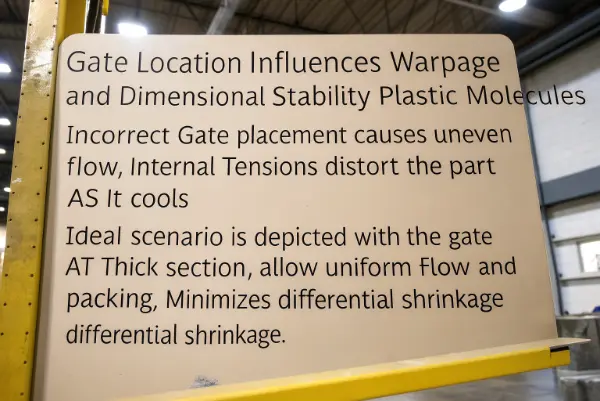
Gate location influences warpage by dictating the flow pattern and packing pressure across the part. Ideally, the gate should be placed at the thickest section to allow flow from thick to thin areas, ensuring uniform packing and minimizing differential shrinkage that leads to warping.
This is a critical area where design meets reality. I have seen excellent product designs fail because the gate was placed in a thin section. This effectively "freezes off" the flow before the thicker sections are packed out.
The Mechanics of Flow and Shrinkage
When you inject molten ABS, it shrinks as it cools. We know ABS has a shrinkage rate of roughly 0.4% to 0.7%. However, it doesn’t shrink evenly in all directions. It shrinks differently with the flow compared to across the flow.
- Flow Direction: Molecules align in the direction of the flow.
- Transverse Direction: Molecules are less aligned perpendicular to the flow.
If you gate at the corner of a long, thin rectangular part, the molecules align differently along the length versus the width. This creates internal stress. As the part cools, these stresses release, causing the part to twist or bow.
Key Strategies for Location:
- Center Gating: For round or symmetrical parts, a center gate (often a fan or diaphragm gate) ensures radial flow. This makes shrinkage uniform in all directions, drastically reducing warpage.
- Thick-to-Thin: Always gate into the thickest wall. This allows the localized pressure to pack out the material while it is still molten. If you gate into a thin section, that thin area solidifies (freezes) first, isolating the still-molten thick section. As that thick section cools, it shrinks, creating a vacuum void or a sink mark because no new material can get in to fill the space.
At CavityMold, we use critical thinking during the DFM (Design for Manufacturability) phase. We ask: "Where will the air traps be?" If we place the gate here, the air pushes to the end of fill. If that end of fill is a blind pocket without venting, you get burn marks. Moving the gate can push that air to a parting line where it can vent naturally. It is a puzzle, and solving it early prevents warped parts on your assembly line.
Why Do Weld Lines Occur and How Can Gate Design Minimize Them?
Have you ever seen a crack-like line on a plastic part and wondered if it was broken? That is likely a weld line. These are not just ugly; they are weak points where two flow fronts meet but don’t fuse together perfectly.
Weld lines occur when the flow of molten plastic splits around an obstruction (like a hole) and rejoins on the other side. Gate design minimizes them by positioning the gate so flow fronts meet at higher temperatures and pressures, or by moving the weld line to a non-critical, hidden area.
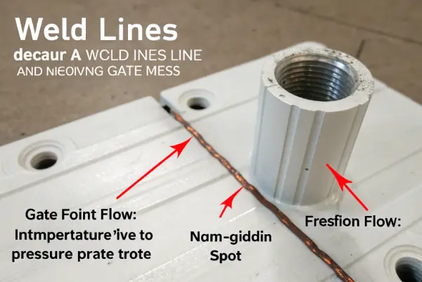
Weld lines are the bane of cosmetic parts. In consumer electronics, a visible line on a smooth surface is a rejection criteria. But beyond looks, a weld line in ABS can reduce the structural strength of that area by up to 50%.
Managing Flow Fronts and Structural Integrity
Let’s dive deeper into the physics. When the ABS flow front splits around a core pin (to make a screw boss or a window), the material cools slightly as it travels. When the two fronts smash back together, the leading edges are cooler than the core material. If they are too cool, they don’t molecularly bond well. This creates a "knit line" or weld line.
How we manipulate this with Gates:
- Gate Number and Position: Using a single gate often results in fewer weld lines than multiple gates. However, for large parts, you might need multiple gates to fill the cavity. The trick is positioning. If you have a hole in the center of a part, gating on one side will force a weld line on the opposite side of the hole. By moving the gate, we can move that weld line.
- Sequential Valve Gating: For large, complex ABS parts, we might use a hot runner system with valve gates. We open the first gate to start the flow. As the flow passes the second gate, we open that one. This continues down the part. Because the flow is continuous and creates a single front, we can eliminate weld lines entirely in some large panels.
The Strength Factor:
Imagine a screw boss where the screw exerts outward pressure. If a weld line runs right through that boss, the hoop stress from the screw will snap the plastic right at that line. It is a classic failure mode.
We analyze this by looking at the "End of Fill" data. We want the weld line to happen where the pressure is high enough to fuse the material. If the weld line happens at the very end of the fill, the pressure is zero, and the bond is weak. Sometimes, we add "overflow tabs"—little extra pockets of plastic attached to the part. The weld line gets pushed into this tab, which is then cut off after molding, leaving the main part strong and clean.
Can Gate Size and Shape Affect Cycle Time and Production Costs?
Does a bigger gate mean a faster cycle? Not necessarily. It is easy to think that a big hole fills faster, but in injection molding, the gate size dictates the cooling time and the trimming process, which directly hits your bottom line.
Gate size and shape significantly affect cycle time and costs because the gate is often the last point to freeze. A gate that is too large extends the cooling phase, increasing cycle time, while a gate that is too small requires higher injection pressures, wearing out the machine and potentially degrading the ABS plastic.
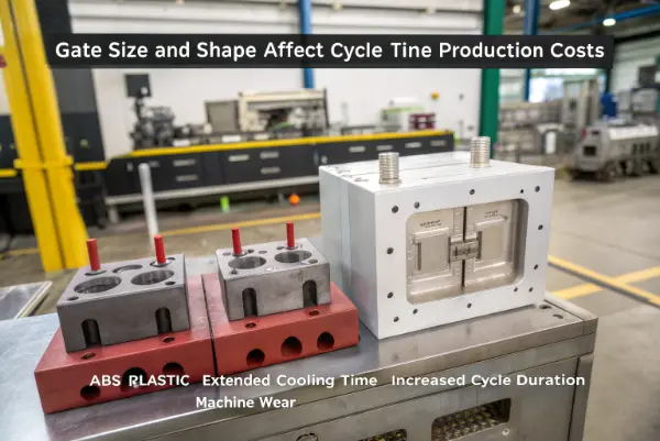
Time is money. In high-volume production, saving 2 seconds on a 30-second cycle is a massive cost reduction over a million parts. The gate is a major variable in that equation.
Balancing Freezing Time and Shear Heat
Let’s break down the economics and engineering here. The molding cycle consists of: Injection -> Packing -> Cooling -> Ejection.
The "Packing" phase is key. You must keep pressure on the part until the gate freezes. If the gate freezes too soon (because it is too small), you can’t pack the part, and you get sink marks. If the gate freezes too late (because it is too big), you are sitting there waiting, wasting machine time.
Gate Sizing Rules of Thumb for ABS:
- Depth: typically 50% to 75% of the wall thickness.
- Width: typically 1.5 to 2 times the depth.
The Cost Implications:
- Shear Heating: A small gate increases the speed of the plastic passing through it. This friction creates heat (shear heat). While some heat helps flow, too much heat degrades the additives in the ABS, leading to color streaks or brittle parts. This creates scrap. Scrap costs money.
- Degating Costs: This is often overlooked. A submarine gate separates automatically. An edge gate requires an operator with clippers or a robot. If you use a large tab gate to prevent jetting, you might need a CNC fixture to trim it cleanly.
- Example: We had a client switch from a standard edge gate to a submarine gate for a small internal bracket. The tool cost $1,500 more upfront. However, they saved $0.05 per part in labor because they didn’t need a person trimming the gate. On a 100,000 unit run, they saved $5,000. The ROI was instant.
Jetting Issues:
If a gate is small and positioned poorly, the plastic shoots into the cavity like a snake (jetting) rather than expanding smoothly. This creates surface defects that look like squiggly lines. To fix this, we often use a "fan gate" or slightly enlarge the gate land. This slows the plastic down just enough to spread out. It might add 0.5 seconds to the fill time, but it eliminates a 10% scrap rate due to cosmetic failures. That is a trade-off worth making.
Conclusion
Optimizing gate design for ABS is a balance of science and experience. By selecting the right gate type, placing it correctly to manage flow and shrinkage, and sizing it for efficient cooling, you ensure your parts are strong, dimensionally accurate, and cost-effective. At CavityMold, we help you navigate these choices to make sure your project succeeds.