Struggling to balance part quality, cycle times, and manufacturing costs in your mold designs? A poorly designed core and cavity can lead to defects, long cycles, and budget overruns. Mastering a few key design principles ensures high-quality, efficient, and manufacturable molds from the start.
Mastering core and cavity design involves balancing several key areas. You must select the right steel, design an efficient cooling system, and plan for proper gating and venting. Applying Design for Manufacturability (DFM) principles is also crucial. These elements work together to ensure high part quality, reduce cycle times, and create a durable, cost-effective mold that meets all project requirements from the start.
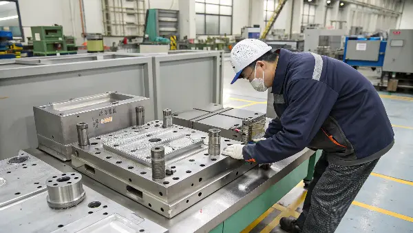
Getting the core and cavity right is the heart of any successful injection molding project. It’s where the magic happens, turning molten plastic into a finished part. But it’s not magic; it’s a science built on solid principles. Over my years in the industry, I’ve seen how focusing on the fundamentals prevents major headaches down the line. So, where do we begin? Let’s dive into the core principles that form the foundation of every great mold.
What Are the Core Principles for Designing a High-Performance Core and Cavity?
Do your mold designs often require rework? Flaws like sink marks or warpage can stem from overlooking basic design rules. This leads to costly delays and compromises on quality. Adhering to fundamental principles from the start ensures a smoother, more predictable manufacturing process for everyone involved.
The core principles for designing a high-performance core and cavity focus on uniformity and durability. This includes maintaining uniform wall thickness to prevent defects, incorporating adequate draft angles for easy ejection, and adding proper radii to reduce stress concentrations. These foundational rules ensure the final part is strong, dimensionally accurate, and can be produced efficiently without damaging the mold or the part.
These principles sound simple, but their impact is huge. I’ve seen projects get derailed because a designer overlooked one of these basic rules. They form the non-negotiable foundation of good mold design. Let’s break them down.
Uniform Wall Thickness
The single most important rule in plastic part design is to maintain a uniform wall thickness. When molten plastic cools, it shrinks. If one section of a part is much thicker than another, it will cool and shrink at a different rate. This uneven shrinkage causes internal stresses that can lead to defects like sink marks (depressions on the surface opposite a thick section), voids (internal bubbles), and warpage (twisting of the part). Keeping walls uniform ensures the part cools evenly, resulting in a stable, high-quality product. If thickness variations are unavoidable, the transition should be as gradual as possible.
Adequate Draft Angles
A draft angle is a slight taper applied to the vertical walls of the part. Imagine trying to pull a perfect cylinder out of a tight-fitting cylindrical hole; friction creates a vacuum and makes it difficult. The draft angle makes the part slightly narrower at its base than at the top, allowing it to release easily from the mold during ejection. Without proper draft, the part can scrape against the mold surface, causing scratches, or it might stick entirely, leading to damage to the part or the mold itself. The required angle depends on the material, texture, and depth of the cavity, but it’s a critical element for efficient production.
Proper Radii and Fillets
Sharp internal corners are stress concentrators. When plastic flows into a sharp corner, it can create a weak point in the final part. These corners also make the mold harder and more expensive to machine. Adding a radius (a rounded internal corner, or fillet) distributes the stress more evenly, making the part much stronger. It also helps the plastic flow more smoothly into the cavity. Similarly, rounded external corners are safer to handle and less prone to chipping.
| Design Principle | Purpose | Common Issue if Ignored |
|---|---|---|
| Uniform Wall Thickness | Ensures even cooling and shrinkage | Sink marks, warpage, voids |
| Draft Angles | Allows for easy part ejection from the mold | Scratches, drag marks, sticking |
| Radii and Fillets | Reduces stress concentration and improves strength | Cracking, weak parts, flow issues |
How Does Steel Selection for the Core and Cavity Impact Mold Lifespan and Part Quality?
Have you ever faced unexpected mold wear or a drop in part finish quality? The wrong steel choice for your core and cavity can be the silent culprit. This misstep can lead to premature tool failure, increased maintenance, and inconsistent part quality, hurting your bottom line and project timelines.
Choosing the right steel for your core and cavity directly impacts durability, surface finish, and cost. Hardened steels like H-13 offer excellent wear resistance for high-volume production, while pre-hardened steels like P-20 provide a good balance of machinability and toughness for medium runs. The material must match the plastic being molded, production volume, and required part finish to ensure optimal performance.
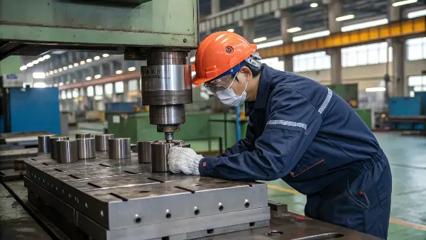
The steel you choose is the skeleton of your entire molding operation. It determines how long your mold will last, how well it can be repaired, and the final look of your parts. I remember a project where a client wanted a high-gloss finish on a million parts but chose a softer steel to save on initial costs. After just 100,000 cycles, the finish started to degrade, and they ended up needing a new, more expensive tool. Making the right choice upfront saves a lot of money and headaches.
Steel Categories
The world of mold steels can be broken down into a few main categories, each suited for different applications.
- Pre-Hardened Steels: These are materials like P-20. They are delivered from the supplier already heat-treated to a moderate hardness. This makes them relatively easy to machine, which reduces the cost and time of manufacturing the mold. They are a great, cost-effective choice for prototypes and medium-volume production runs, typically up to around 400,000 cycles.
- Hardened Steels: For high-volume production and abrasive materials, you need a tougher solution. Hardened steels like H-13 or S-7 are machined in a softer state and then heat-treated to achieve very high hardness and durability. This process is more complex and expensive, but the resulting mold can withstand millions of cycles and resist wear from aggressive materials like glass-filled plastics.
- Stainless Steels: When molding materials like PVC that release corrosive gases, or when the mold will be used in a humid environment, stainless steel is the answer. Steels like S-136 offer excellent corrosion resistance on top of good hardness and polishability, protecting your investment.
Factors Influencing Your Choice
Choosing the right steel is a balancing act. You need to consider several factors to find the optimal material for your specific project.
| Steel Type | Typical Hardness (HRC) | Best For | Key Benefit |
|---|---|---|---|
| P-20 | ~30-36 HRC | Prototypes, low-to-medium volume runs (<400k cycles) | Good machinability, cost-effective |
| H-13 | ~48-52 HRC | High-volume runs (>1M cycles), abrasive plastics (e.g., glass-filled) | Excellent wear resistance, high toughness |
| S-136 | ~48-52 HRC | Molds for corrosive plastics (PVC), high-polish optical parts | Superior corrosion resistance, polishability |
What Makes a Cooling System Design So Critical for the Core and Cavity?
Are long cycle times eating into your production efficiency? An inefficient cooling system is often the bottleneck. This slows down production, increases costs, and can even cause part defects like warpage. A well-designed cooling system is your key to faster, more consistent, and higher-quality molding.
An effective cooling system is critical because it controls over 70% of the injection molding cycle time. By placing cooling channels strategically within the core and cavity, you ensure uniform and rapid heat removal. This minimizes cycle times, prevents thermal-related defects like warpage and sink marks, and guarantees consistent part quality from the first shot to the last. It’s a direct driver of both efficiency and quality.
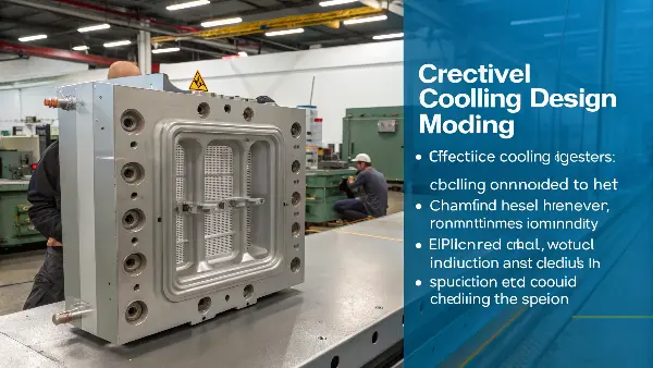
Think of cooling as the unseen engine of your production line. You can have the best steel and a perfect part design, but if you can’t get heat out of the mold quickly and evenly, you’ll never achieve your target cycle time or quality. Uniform cooling is just as important as the fill stage. Hot spots in the mold create weak spots in the part. I always tell my clients to invest as much thought into the cooling design as they do into the part geometry itself.
Conventional vs. Conformal Cooling
The approach to cooling has evolved significantly.
- Conventional Cooling: This is the traditional method. It involves drilling straight lines for water channels through the mold block. It’s simple, inexpensive, and effective for many simple part geometries. However, these straight lines can’t always get close enough to complex features or deep cores, leaving "hot spots" that cool much slower than the rest of the part.
- Conformal Cooling: This is a more advanced technique, often enabled by 3D metal printing. Conformal cooling channels follow the contour or shape of the part. This allows the coolant to flow much closer to the surface of the mold, even in complex areas. The result is extremely fast and uniform cooling, which can reduce cycle times by 30-50% and significantly improve part quality by eliminating warpage. While the initial mold cost is higher, the ROI from faster cycles and lower scrap rates is often very compelling for high-volume production.
Key Cooling Design Considerations
Whether you choose conventional or conformal, several factors must be considered:
- Channel Distance: The cooling channels need to be close enough to the molding surface to be effective but far enough away to maintain the structural integrity of the mold.
- Channel Diameter: A larger diameter allows for higher coolant flow, but there’s a point of diminishing returns. The diameter must be balanced with the overall mold size and pump capacity.
- Coolant Flow: The flow must be turbulent, not laminar. Turbulent flow is much more efficient at transferring heat. We can use baffles and bubblers to create turbulence in specific areas.
| Cooling Method | Description | Advantages | Disadvantages |
|---|---|---|---|
| Conventional Cooling | Straight-line channels drilled into the mold. | Simple, low-cost, easy to manufacture. | Can create hot spots, less efficient for complex parts. |
| Conformal Cooling | Channels follow the part’s contour. | Highly uniform cooling, reduces cycle time, improves part quality. | Higher initial cost, more complex to design and build. |
How Can You Calculate Core and Cavity Dimensions with Precision, Beyond Basic Shrinkage Rates?
Do your molded parts sometimes fail to meet tight tolerances? Relying solely on a material’s standard shrinkage rate is a a common, and often costly, mistake. This simple approach can lead to inaccurate parts, expensive mold modifications, and frustrating project delays. Achieving true precision requires a much more sophisticated approach to dimensional calculations.
To precisely calculate core and cavity dimensions, you must go beyond basic shrinkage formulas. This involves considering factors like molding process parameters (injection pressure, temperature), part geometry (wall thickness), and gate location. Advanced tools like Mold Flow Analysis (MFA) simulate these variables, providing a highly accurate prediction of final part shrinkage. This data-driven approach allows for precise compensation in the mold design, ensuring dimensional accuracy.
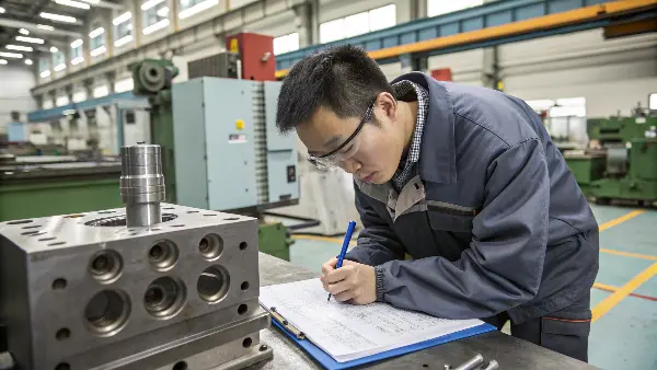
Every plastic material datasheet provides a shrinkage rate, usually as a range (e.g., 0.005-0.007 in/in). Many designers simply take the average and use that to scale the mold cavity. This is a gamble. The actual shrinkage of a part is a complex event influenced by dozens of variables. At CAVITYMOLD, we moved away from this guesswork years ago. Using advanced simulation tools isn’t a luxury; it’s a necessity for any project that requires precision and a fast path to production.
The Problem with Basic Shrinkage Rates
A single shrinkage value doesn’t account for reality. In a real-world molding scenario, shrinkage isn’t uniform across the entire part.
- Differential Shrinkage: Plastic shrinks more in the direction of flow than it does perpendicular to the flow. This means a part might shrink 0.6% in length but only 0.4% in width.
- Processing Conditions: Higher melt temperatures, packing pressures, and longer cooling times all affect how much the part shrinks.
- Part Geometry: As we discussed earlier, thick sections shrink more than thin sections. The location of gates and ribs also creates variations in shrinkage.
Using a single, average value ignores all this nuance, which is why parts often come out of the mold warped or out of spec.
The Power of Mold Flow Analysis (MFA)
This is where modern technology comes in. Mold Flow Analysis is a powerful simulation software that predicts how plastic will behave inside the mold before any steel is cut. By building a digital model of the part, runners, and cooling channels, we can simulate the entire injection process. MFA provides detailed predictions on fill patterns, pressure distribution, cooling rates, and, most importantly, the exact shrinkage and warpage of the final part. This allows us to make a much more intelligent compensation in the core and cavity dimensions, accounting for all the complex variables. It turns a guessing game into a predictive science.
| Factor Influencing Shrinkage | How to Account for It |
|---|---|
| Material Anisotropy | Use MFA to predict different shrinkage rates in flow and cross-flow directions. |
| Process Parameters | Run simulations with expected injection pressure, temperatures, and cooling times. |
| Part Geometry | MFA automatically calculates how different thicknesses will shrink and warp. |
| Gate Location | Simulate different gate locations to see how they impact fill and shrinkage patterns. |
Conclusion
Effectively designing a mold’s core and cavity is a careful balance. It demands attention to foundational principles, material science, thermal management, and precise calculations. By focusing on these key areas, you can ensure your molds are robust, efficient, and produce high-quality parts consistently for your projects.
