Struggling with defects like warping or shorts shots in your injection molded parts? The problem often lies in the fundamentals of your core and cavity design. Getting these basics wrong can lead to costly rework and production delays, impacting your entire project timeline.
The core and cavity are the two halves of an injection mold that form the shape of the final plastic part. The core forms the internal features (the "male" side), while the cavity forms the external surfaces (the "female" side). Proper design of these components is crucial for part quality, mold longevity, and efficient manufacturing. It dictates everything from ejection to surface finish.
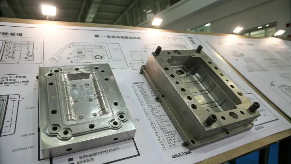
I’ve seen countless projects over the years, and a solid grasp of these principles is what separates a successful part from a failed one. It’s the foundation of everything we do in mold making. Let’s break down the key elements you need to master. Understanding these fundamentals will not only improve your designs but also make you a more effective project manager.
What is the fundamental difference between the core and cavity?
Confused about which part of the mold is the core and which is the cavity? This simple mix-up can lead to major design flaws and communication breakdowns with your mold maker. It’s a basic concept, but one that causes significant problems if misunderstood.
The core is the "male" half of the mold that forms the internal shape of a part, while the cavity is the "female" half that shapes the external surface. Think of it like this: the core creates holes and indentations, and the cavity creates the smooth outer shell. The plastic part shrinks onto the core during cooling, which is why ejector pins are typically located on the core side.
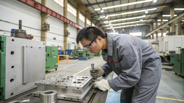
This distinction seems simple, but it has profound implications for the entire mold design. The core is often called the moving half or ejector half, while the cavity is the fixed or stationary half. This is because the core side usually contains the ejector system that pushes the finished part out of the mold.
As the molten plastic cools, it shrinks. This shrinkage causes the part to grip tightly onto the core. If we didn’t have ejector pins on the core side, it would be extremely difficult, if not impossible, to remove the part without damaging it. This is a fundamental principle engineers must consider from the very start.
Here’s a simple breakdown of their roles:
| Feature | Core Side (Male Half) | Cavity Side (Female Half) |
|---|---|---|
| Function | Forms internal part features (holes, bosses, ribs) | Forms external part features (A-surface, texture) |
| Ejection | Typically contains the ejector system | Usually stationary, contains the sprue bushing |
| Cooling | Part shrinks onto it, making cooling critical | Part pulls away from it, cooling is also important |
| Alternate Name | Moving Half / Ejector Half | Fixed Half / Injection Half / A-Side |
Understanding this relationship is key to designing for manufacturability (DFM). For instance, deep internal features on the core require longer, more robust ejector pins. Similarly, the "A-side" of the part, the cosmetic surface most visible to the consumer, is almost always formed by the cavity. This allows us to achieve the best possible surface finish on the most important face.
Why is draft angle essential for core and cavity design?
Are your plastic parts getting stuck in the mold or showing unsightly drag marks? This common issue is frustrating and can bring production to a halt. It’s often caused by overlooking a small but critical design feature: the draft angle.
A draft angle is a slight taper applied to the vertical faces of a part, parallel to the direction of the mold opening. It’s essential because it allows the part to be ejected cleanly from the core and cavity without creating friction or a vacuum. Without it, parts can get damaged or stuck, leading to increased cycle times and tool wear. A minimum of 1-2 degrees is a standard recommendation.
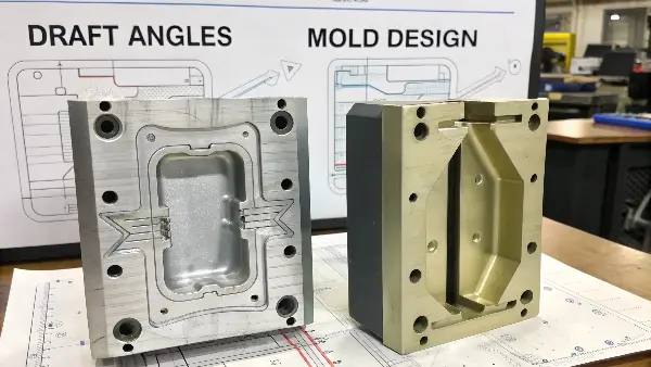
Think of trying to pull a perfectly straight-sided object out of a tight container. It creates friction and a vacuum seal, making it incredibly difficult. A draft angle turns that vertical wall into a slight ramp, making release much smoother. It’s one of the most important considerations in designing for injection molding. In my experience at CavityMold, insufficient draft is one of the top reasons for part rejection during first article inspection (FAI).
The amount of draft needed depends on several factors:
- Surface Finish: A textured surface requires more draft than a polished one. The tiny peaks and valleys of the texture can interlock with the mold steel, so you need a greater angle to ensure a clean release. For a light texture, you might need 3 degrees. For a heavy texture, it could be 5 degrees or more.
- Material: Softer, more flexible materials might require less draft than rigid, brittle ones. However, some soft materials can be "sticky," necessitating more draft.
- Wall Depth: The deeper the feature, the more draft is required. A 1-degree draft over a 100mm deep rib will have a much greater effect than a 1-degree draft over a 2mm rib. A general rule is to add 1 degree of draft for every 25mm of depth for textured surfaces.
| Requirement | Recommended Draft Angle | Reason |
|---|---|---|
| Polished Surface | 0.5 – 1 degree (min) | Minimum required for steel-on-steel release |
| Light Texture | 3 degrees (min) | Prevents texture from scraping or dragging during ejection |
| Deep Features | Increase per inch/mm | Compensates for the cumulative effect of friction over a longer surface |
| Shut-off faces | 3 – 5 degrees (min) | Ensures a clean seal between mold components without excessive wear |
Ignoring draft angles doesn’t just damage the part; it puts immense stress on the mold itself, especially the ejector pins and the core/cavity surfaces. This leads to premature tool wear and costly maintenance. It’s a simple detail that saves a lot of money and headaches down the road.
What are the critical design considerations for the parting line?
Ever designed a perfect part, only to find an ugly, visible seam ruining its appearance? The placement of the parting line can make or break the aesthetic and functional quality of your product. A poorly chosen parting line is a mistake you can’t easily hide.
The parting line is the dividing line on the part where the two halves of the mold, the core and cavity, meet. Critical considerations include its visibility on the final product, its impact on tool cost and complexity, and its ability to prevent flashing. A good parting line is often placed along a sharp, natural edge to hide it and simplifies the mold construction.
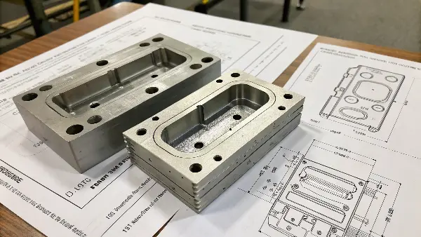
Choosing the parting line is one of the first and most important decisions in mold design. It dictates the direction of mold opening and influences almost every other design feature, from draft angles to gate location. As a project manager, I always double-check the proposed parting line before approving any tool design.
Here are the key factors we analyze:
- Part Geometry: The ideal parting line follows the natural contour of the part’s outer edge. For a simple cup shape, the parting line is the top rim. For complex shapes, it might need to be stepped or curved, which increases the complexity and cost of the mold. A straight, flat parting line is always the simplest and most cost-effective.
- Cosmetics: Where will the line be least noticeable? We try to place it on a non-cosmetic surface or along a sharp edge where it can be naturally concealed. For a project manager working on consumer electronics, this is paramount. A parting line across a smooth, visible face is usually unacceptable.
- Undercuts and Side Actions: The parting line determines what features become undercuts that prevent the part from being ejected in a straight line. These features require side actions or lifters, which are moving components that add cost and complexity. By carefully selecting the parting line, we can often minimize or eliminate the need for these mechanisms.
- Venting: Air trapped in the mold must escape as plastic flows in. The parting line serves as a natural primary vent path. Its placement must facilitate effective air removal to prevent burns or incomplete filling.
Parting Line Selection Checklist
| Priority | Consideration | Best Practice |
|---|---|---|
| 1 | Simplicity | Strive for a flat, straight line to reduce tool cost. |
| 2 | Aesthetics (Visibility) | Place on a non-cosmetic surface or along a sharp feature. |
| 3 | Draft Direction | Ensure all surfaces have proper draft relative to the parting line. |
| 4 | Minimize Side Actions | Choose a line that avoids creating unnecessary undercuts. |
| 5 | Gating Location | Ensure the line allows for optimal gate placement. |
Getting the parting line right from the start avoids complex and expensive tool modifications later. It’s a collaborative decision between the product designer and the mold maker.
How does material selection impact core and cavity design?
Choosing the wrong plastic for your part can have disastrous consequences for your mold. From unexpected shrinkage to corrosive wear, the material dictates how your mold must be designed and built. Ignoring this link is a recipe for a failed project.
Material selection directly impacts core and cavity design through shrinkage rates, corrosiveness, and abrasiveness. High-shrinkage materials like Polypropylene require different mold dimensions than low-shrinkage materials like ABS. Abrasive, glass-filled plastics demand hardened tool steels (e.g., H-13) for the core and cavity to resist wear, while corrosive PVC may require stainless steel to prevent rust.
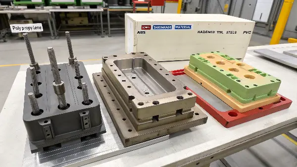
A mold is not a one-size-fits-all tool. It must be precision-engineered for a specific plastic resin. When we get a new project at CavityMold, one of the first questions we ask is, "What material will you be molding?" The answer changes everything about how we design the core and cavity.
The two biggest factors are shrinkage and wear.
1. Shrinkage: Every plastic shrinks as it cools from its molten state. We have to design the mold cavity to be larger than the final part to compensate for this. The shrinkage rate varies significantly between materials. For example, ABS might shrink around 0.5%, while Polypropylene can shrink up to 2.0% or more. We must apply this specific shrink factor to every dimension of the core and cavity CAD model. Getting this wrong means the final parts will be out of tolerance.
2. Wear and Corrosion: The plastic resin can be tough on the mold steel.
- Abrasive Materials: Plastics filled with glass fibers or other additives act like sandpaper on the mold surfaces. They will wear down the core and cavity over time, especially in high-flow areas. For these materials, we must use high-hardness, wear-resistant tool steels like H-13 or S-7.
- Corrosive Materials: Some plastics, like PVC, release corrosive gases during molding that can rust standard tool steels. For these applications, we need to build the core and cavity from stainless tool steel, such as S-136 or 420SS, to prevent degradation.
Here’s a simplified table to illustrate the point:
| Plastic Material | Key Consideration | Recommended Mold Steel |
|---|---|---|
| ABS | Low Shrinkage, Non-Abrasive | P-20 (pre-hardened) |
| Polypropylene | High Shrinkage, Non-Abrasive | P-20 (pre-hardened) |
| 30% Glass-Filled Nylon | Abrasive, Medium Shrinkage | H-13 (through-hardened) |
| PVC | Corrosive, Low Shrinkage | 420SS (stainless steel) |
The material choice fundamentally dictates the steel we use and the dimensions we cut. This directly impacts the cost and longevity of the tool.
How do cooling systems integrate with core and cavity design?
Are long cycle times eating into your profit margins? Is part warping causing high scrap rates? The unseen network of cooling channels within your mold’s core and cavity is likely the culprit. Inefficient cooling is a silent killer of productivity and quality.
Cooling systems are networks of channels drilled through the core and cavity plates that circulate a fluid to control the mold’s temperature. Their design is critical for managing cycle time and part quality. Even and efficient cooling prevents warping, reduces shrinkage defects, and allows for faster production cycles. Poor cooling leads to inconsistencies and long, unprofitable cycle times.
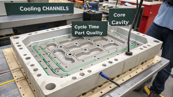
Cooling is often the most time-consuming part of the injection molding cycle—it can account for up to 80% of the total cycle time. Therefore, designing an efficient cooling system integrated into the core and cavity is an economic necessity. The goal is to remove heat from the plastic part as quickly and as evenly as possible.
We design cooling channels to follow the part’s geometry. This ensures all areas of the part cool at a similar rate. Uneven cooling is a primary cause of internal stress, which leads to part warping. For example, a thick section holds heat longer than a thin wall. We must run more cooling lines or use specialized components near thicker areas to balance the heat removal.
There are different approaches to cooling design:
- Standard Channels: These are straight, drilled lines. They are simple and cost-effective but may not be optimal for complex geometries.
- Baffles and Bubblers: These direct coolant flow into hard-to-reach areas, like long cores. A baffle forces water up one side of a channel and down the other. A bubbler shoots coolant to the top of a blind hole.
- Conformal Cooling: This advanced technique uses metal 3D printing to create cooling channels that conform precisely to the part’s shape. While more expensive upfront, it can drastically reduce cycle times and improve quality, offering a powerful ROI for high-volume production.
Cooling Design Impact
| Cooling Method | Complexity | Cost | Performance |
|---|---|---|---|
| Standard Drilled Lines | Low | Low | Good for simple parts |
| Baffles / Bubblers | Medium | Medium | Good for deep cores and targeted cooling |
| Conformal Cooling | High | High | Excellent for complex parts, fast cycles |
A well-designed cooling layout in the core and cavity is an investment that pays for itself through faster production, lower scrap rates, and better, more consistent parts.
Conclusion
Mastering core and cavity design is about controlling the fundamentals: shape, release, material interaction, and temperature. By focusing on these key principles—from draft angles to cooling—you build a foundation for high-quality, efficient, and profitable injection molding. It’s what we live and breathe at CavityMold every day.
