

Plastic mold texture is a controlled cavity-surface finish that transfers to the molded part and affects appearance, grip, draft, ejection, and tooling cost. Texture is not simply a decorative choice: it is part of the part specification and must be designed with resin, geometry, and production in mind.
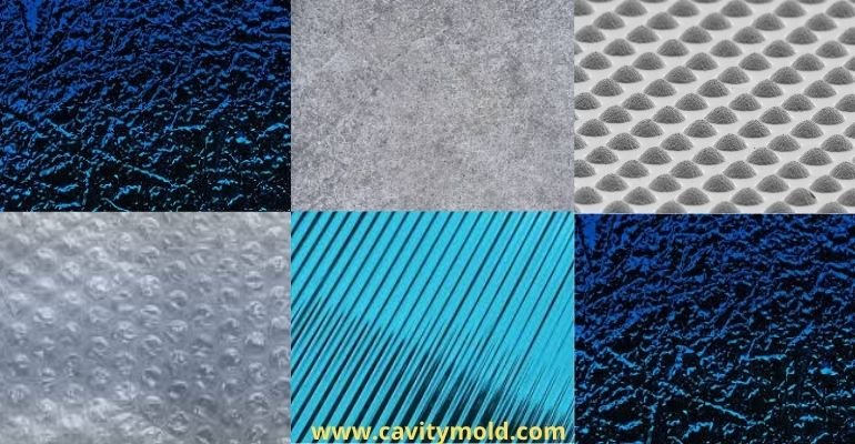
A drawing should identify the texture standard, grade, location, direction, transitions, and any no-texture or cosmetic zones. A vague description such as “matte finish” leaves too much room for different interpretations during tooling and approval.
What mold texture changes
- Appearance: gloss, diffuse reflection, grain, color perception, and visual uniformity.
- Touch and grip: tactile feel and resistance to sliding.
- Release: texture creates microscopic features that can increase drag during ejection.
- Dimensional fit: textured walls may need more draft and can change local geometry.
- Tooling: masking, polishing, etching or blasting, sampling, and repair become part of the schedule and cost.
SPI, VDI, and supplier texture references
SPI finish designations commonly describe polished, semi-gloss, matte, or textured mold surfaces. VDI 3400 references are often used for electrical-discharge-machined textures. Mold-Tech and other proprietary references may describe a grain pattern, depth, or appearance. These systems should not be treated as exact one-to-one conversions without the relevant sample or supplier specification.
| Specification element | What to define |
|---|---|
| Standard | SPI, VDI, Mold-Tech, supplier sample, or customer-specific reference |
| Location | Faces, ribs, shutoffs, parting-line zones, and cosmetic boundaries |
| Direction | Grain direction, pull direction, weld-line visibility, and visual orientation |
| Release requirement | Draft, wall depth, shrink direction, ejection side, and texture depth |
| Acceptance | Master sample, visual limit sample, gloss/roughness method, and lighting condition |
Texture and draft angle
Texture can act like a field of microscopic undercuts. The required draft depends on texture depth, wall depth, resin shrinkage, surface orientation, and whether the part grips the core or cavity as it cools. Use a draft analysis for textured walls and record exceptions before steel is cut.
If a cosmetic wall cannot accept more draft, consider moving the parting line, changing texture, using a different ejection strategy, or adding a replaceable insert. The engineering team should review the trade-off with the mold-making team before final texture approval.
How texture is applied and inspected
- Machine and polish the cavity or core to the agreed base condition.
- Mask areas that must remain polished, protected, or dimensionally controlled.
- Apply the selected chemical etch, blast, EDM, laser, or mechanical finish.
- Inspect the tool using the texture supplier’s reference and the approved sample method.
- Run sample parts and evaluate appearance, release, dimensions, and transition quality under agreed lighting.
Surface roughness numbers alone do not capture grain direction, visual scale, or part appearance. A molded master sample is often the most useful acceptance reference for a cosmetic product.
How texture changes cost and lead time
Texture can add masking, supplier coordination, rework risk, inspection, and a separate approval step. A deep or directional texture can also require more draft, change the parting-line decision, or create additional ejection work. Include texture zones and references in the original RFQ so suppliers do not price the tool on an unstated cosmetic assumption.
For a texture review, send the part model, drawing, resin/color, appearance target, texture reference, annual volume, and any critical fit surfaces. Contact Cavity Mold for a DFM and tooling review.
Technical reference
The Plastics Technology Alliance surface-finish guide explains how SPI and VDI specifications affect appearance, draft, cost, and lead time.