Struggling with slow, error-prone manual checks for your intricate molds? It’s frustrating when production halts because inspections take forever, right? Well, modern 3D inspection techniques can slash that time and boost accuracy, getting you back on track fast.
To quickly perform 3D inspection on a complex mold, you should use 3D scanning technology combined with specialized metrology software. This approach captures the mold’s complete geometry and compares it against the original CAD model to instantly pinpoint any deviations or wear.
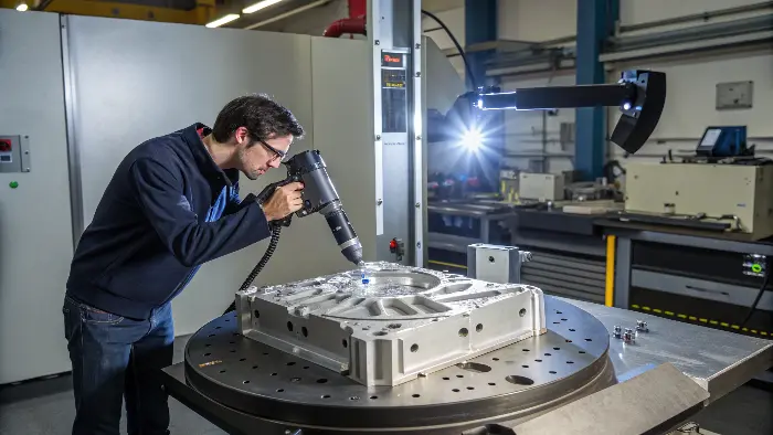
So, you’re probably wondering how this all actually works and what tools you might need. It’s not as complicated as it sounds, and I think breaking it down will show you just how accessible these methods are. Let’s dive into some specifics, shall we?
What’s the Best 3D Scanning Tech for Complex Molds, Anyway?
Choosing the right scanner feels overwhelming with so many options, doesn’t it? You worry about picking one that can’t handle your mold’s tricky surfaces or tight corners. But the right tech makes capturing all that detail a breeze, trust me.
For complex molds, structured light scanners are often best due to their high accuracy and ability to capture fine details without contact. Laser scanners, especially those on portable CMM arms, offer flexibility for larger molds or in-situ inspections.
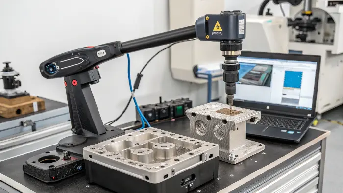
When we talk about inspecting complex molds, the first thing that usually comes to my mind is the sheer detail involved. You’ve got undercuts, deep ribs, intricate textures – stuff that’s a nightmare for traditional methods. That’s where 3D scanning really shines. I’ve seen a few types in action, and for molds, two main players stand out. It’s not just about buying the fanciest gadget; it’s about understanding what each type does best.
Key 3D Scanning Technologies for Molds
| Technology | Pros | Cons | Best For |
|---|---|---|---|
| Structured Light | High accuracy, fast capture rates, excellent with fine details, non-contact. | Can struggle with very shiny, transparent, or dark surfaces without preparation. | Small to medium, highly detailed molds. |
| Laser Scanning | Versatile, good for larger objects, less sensitive to ambient light conditions. | Can be slower for high-resolution scans, some types might require placing targets. | Large molds, on-machine inspection, reverse engineering. |
I remember one project, a really tricky automotive part mold with lots of tiny features. We used a structured light scanner, and it picked up details we absolutely would’ve missed with calipers or even a touch probe CMM. The data was just so rich. The key is understanding the geometry you’re dealing with. If it’s super complex with lots of small, intricate features, structured light is probably your friend. If it’s a massive mold for, say, a car bumper, a laser scanner mounted on a portable arm might be more practical because of the reach and flexibility. It’s all about matching the tool to the job, you know? And sometimes, a handheld scanner offers the best balance of speed and detail for quick checks or hard-to-reach areas. Don’t just go for the specs; think about your actual workflow.
How Does Metrology Software Actually Help in Mold Inspection?
Got all that scan data, but now what? It’s just a cloud of points, and figuring out if your mold is actually good can feel like searching for a needle in a haystack. You need a way to make sense of it all, quickly and reliably.
Metrology software is crucial as it processes the raw 3D scan data, aligns it with the nominal CAD model, and performs detailed comparisons. It generates color maps showing deviations, provides GD&T analysis, and creates comprehensive inspection reports automatically.
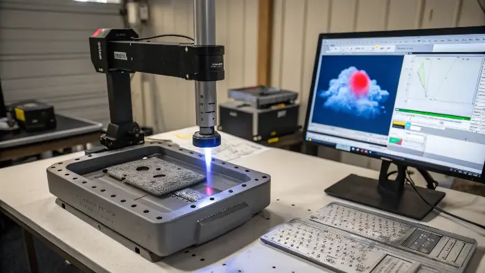
Okay, so you’ve scanned your mold. Now you have this massive digital file, maybe a point cloud or a mesh. What’s next? This is where metrology software becomes your best buddy. Think of it as the brain of the operation. Without it, the scan data is just a pretty, but kind of useless, picture. I’ve used a few different software packages over the years, and they all fundamentally do a few key things that are super important for mold inspection. It’s not just about looking at the data; it’s about interpreting it.
Core Functions of Metrology Software
- Data Alignment: The very first thing the software does is take your scan data and align it perfectly with the original 3D CAD model of the mold. This is critical. If they aren’t aligned properly, any comparison you make is totally useless. It’s like trying to compare two photos that are taken from different angles and distances – you just can’t. Most software has powerful algorithms for this.
- Deviation Analysis (Color Maps): Once aligned, the software compares the scanned surface to the CAD model, point by point, or mesh to CAD. It then creates these super useful color maps. Green usually means it’s spot on within tolerance, while reds and blues (or other colors) show where the mold is too big or too small, and by how much. This visual feedback is incredibly powerful. I remember seeing my first color map – it was a real "aha!" moment. Suddenly, complex deviations became easy to understand.
- GD&T Verification: For complex molds, just knowing the surface deviation isn’t enough. You need to check Geometric Dimensioning and Tolerancing (GD&T) features – things like flatness, parallelism, cylindricity, position of holes, etc. Good metrology software can analyze these features directly from the scan data and compare them to the tolerances specified in the CAD model or drawing. This is huge.
- Reporting: Finally, it spits out a detailed report. This isn’t just a simple pass/fail; it includes all the measurements, the color maps, cross-sections, GD&T results, everything. This documentation is gold for quality control, for discussions with the mold maker, or for the end client. It takes the guesswork and subjectivity out of it.
Honestly, trying to do this level of analysis manually, especially for complex geometries, would be a complete nightmare and take ages. The software automates so much of the tedious work and provides insights you just couldn’t get otherwise.
Why Is Comparing Scanned Data to CAD Models So Vital for Mold Inspection?
You’ve got a physical mold right there in front of you, why bother with digital models and comparisons? It might seem like an extra, perhaps unnecessary, step. But without that digital twin as a benchmark, how do you truly know if your mold is up to spec or if wear and tear is creeping in?
Comparing scanned data to the original CAD model is vital because the CAD model represents the "perfect" intended design. This comparison immediately highlights any manufacturing errors, wear and tear, or deviations from the design specifications, ensuring mold integrity and part quality.
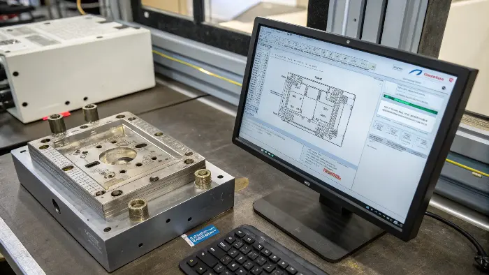
This might sound obvious to some, but it’s worth really digging into why this comparison is the absolute heart of modern 3D mold inspection. Back in the day, we’d rely on 2D drawings and a whole lot of manual measurements with calipers, micrometers, and height gauges. It was slow, prone to human error, and you could easily miss things on complex, freeform surfaces. The CAD model is your ultimate source of truth, your digital master.
The Power of the Digital Benchmark
- The Nominal Reference: Your 3D CAD model isn’t just a pretty picture; it’s the engineering blueprint. It defines every curve, every surface, every dimension with precise mathematical data. When we scan the physical mold, we’re capturing its actual, as-built geometry. The real magic happens when we overlay these two in the metrology software. The CAD model acts as the perfect, unchanging reference against which the real-world mold is judged.
- Identifying Manufacturing Deviations: No manufacturing process is perfect, especially with something as complex as a mold. When a new mold is made, there will always be tiny (or sometimes not-so-tiny) differences between the physical mold and the CAD design. Comparing the scan to the CAD immediately shows these deviations. Maybe a core pin is slightly off-center, or a cooling channel isn’t quite where it should be, or a critical parting line surface has a slight dip. This is crucial for the first article inspection (FAI). I’ve seen cases where this caught issues that would have led to thousands of bad parts down the line – a real money-saver!
- Tracking Wear and Tear: Molds don’t last forever, especially those running high-volume production with abrasive materials like glass-filled plastics. Over time, critical surfaces wear down, parting lines can get damaged, and dimensions can drift. By periodically scanning the mold and comparing it to the original CAD (or a "golden" initial scan of the new mold), you can precisely track this wear. This allows for predictive maintenance. Instead of waiting for the mold to start producing out-of-spec parts, you can see wear developing and plan refurbishment before it becomes a critical problem. This is a game-changer for minimizing unplanned downtime.
- Validating Repairs or Modifications: If a mold is damaged and needs repair, or if it’s modified for a design change (like adding a new feature to the part), scanning and comparing to the updated CAD model verifies that the work was done correctly and to specification. It’s like a quality check for the repair or modification itself. No more "hope it’s right" – you get actual data.
Without that CAD comparison, you’re essentially flying blind, relying on spot checks and hoping for the best. With it, you get a complete, holistic, and data-rich view of your mold’s condition. It’s about moving from assumptions and guesswork to data-driven decisions.
Can Automation Really Speed Up These 3D Mold Checks?
Manually positioning scanners or probes for every nook and cranny of a complex mold sounds exhausting and incredibly time-consuming, right? You’re probably thinking there has to be a faster, more consistent way, especially when you have multiple molds to check or need to perform checks regularly.
Yes, automation significantly speeds up 3D mold checks. Robotic arms equipped with scanners can follow pre-programmed paths for consistent and fast data acquisition, while automated CMMs can perform rapid, repeatable measurements, reducing operator fatigue and inspection time.
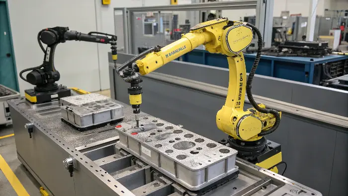
So, we’ve talked about the scanners and the software, but what about the actual process of getting the data? For really complex molds, or when you need to inspect many molds, doing it all by hand can still be a significant bottleneck. This is where automation steps in, and boy, does it make a difference. I’ve seen some impressive setups that really streamline things and take the human element (and potential for error or inconsistency) out of the repetitive parts of the job.
Ways Automation Boosts Inspection Speed & Consistency
- Robotic Scanning Systems: Imagine a multi-axis robotic arm, like the ones you see in automotive assembly lines, but instead of a welding gun or a gripper, it’s holding a 3D scanner (laser or structured light). You can program this robot to move the scanner around the mold, following an optimal path to capture all the necessary surfaces, even complex internal cavities if the scanner can reach. This is way faster and vastly more repeatable than a human operator trying to do the same thing, especially for large or awkwardly shaped molds. Plus, the robot doesn’t get tired, doesn’t need coffee breaks, and ensures consistent data quality every single time. We had a client who implemented this for inspecting a series of similar, fairly large molds, and it cut their inspection time per mold by over 60%, and the data was more reliable too!
- Automated CMMs (Coordinate Measuring Machines): While traditional CMMs with touch probes can be slow for full surface inspection of a mold, modern CMMs can be equipped with non-contact scanners or can be programmed for rapid automated touch probing of critical features. For certain types of checks, especially those requiring very high precision on specific geometric features (like hole positions, datums), an automated CMM cycle is incredibly efficient and accurate.
- Inline or Near-Line Inspection Cells: Automation allows for integrating inspection much closer to the production line, or even right on it. Instead of taking a mold offline to a separate, temperature-controlled metrology lab (which takes time), you can have an automated inspection cell right there. This means much faster feedback loops. If a problem is detected with a mold during a production run (e.g., through part inspection), it can be quickly checked and the issue addressed.
- Pre-Programmed Inspection Routines: With automation, you can create standardized inspection programs for different molds or for specific inspection tasks. The operator just needs to load the mold into the fixture, select the correct program from a menu, and hit "go." This reduces the need for highly skilled metrology experts for every routine check and minimizes the chance of human error in the setup or execution of the scan.
The initial investment in automation can seem high, that’s true. But when you factor in the time savings, increased throughput, improved consistency, reduced labor costs for repetitive tasks, and the ability to make better decisions faster, it often pays for itself pretty quickly, especially in high-volume environments or where mold accuracy is absolutely critical. It’s about making the whole inspection process smarter, not just faster.
Conclusion
So, to quickly check complex molds, 3D scanning, smart software, CAD comparison, and automation are your best bets. This combo saves time, boosts accuracy, and keeps your production running smoothly. It’s a real game-changer in the world of mold making and maintenance!
