Are you struggling to choose the best manufacturing process for your high-performance auto parts? The wrong decision can lead to failed components, project delays, and budget overruns. This guide breaks down two top contenders, CNC aluminum and injection molded PEEK, to help you make the perfect choice.
For high-performance automotive components, CNC machined aluminum excels in precision prototypes and low-volume production due to its design flexibility. In contrast, injection molded PEEK is more cost-effective and superior for manufacturing complex geometries in high volumes. Your final decision should depend on production quantity, part complexity, required tolerances, and overall budget.
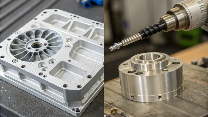
Making the right material and process choice is one of the most critical decisions in any engineering project. It impacts everything from cost and speed to the final performance and reliability of the part. Get it right, and your project runs smoothly. Get it wrong, and you’re in for a world of headaches. Now that you have the high-level summary, let’s dig deeper into the details that truly matter. Understanding the core differences between these two powerful manufacturing methods is the essential first step.
What is the difference between CNC and injection molding?
You hear the terms "CNC machining" and "injection molding" used all the time, but the real distinctions can be a bit blurry. Mixing them up can lead to picking a process that simply can’t deliver your part’s features, costing you significant time and money.
CNC (Computer Numerical Control) machining is a subtractive process. It uses computer-guided tools to carve away material from a solid block, like aluminum, to create a part. Injection molding is an additive process. It involves melting plastic pellets, like PEEK, and injecting the liquid material under high pressure into a custom mold cavity, where it cools into the final shape.
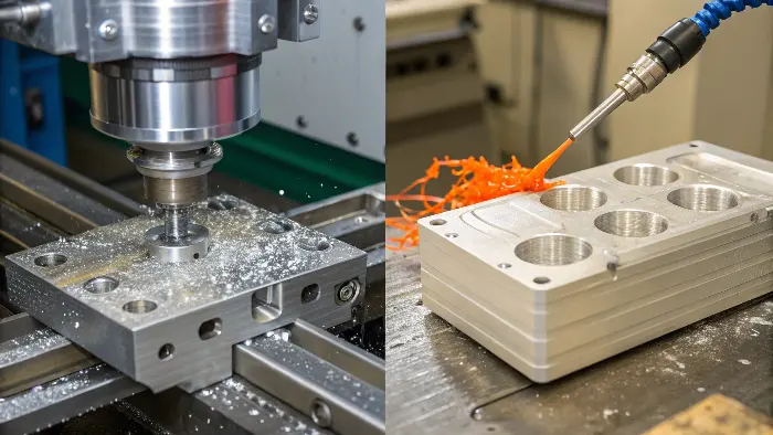
To really understand which process fits your project, you need to look at how they work from the ground up. They are fundamentally opposite approaches to creating a part.
CNC Machining: The Subtractive Sculptor
Think of CNC machining as digital sculpting. You start with a solid block of material, and a computer-controlled cutting tool precisely removes everything that isn’t the final part.
- Design: It all starts with a 3D CAD (Computer-Aided Design) model.
- Programming: That model is translated into machine instructions called G-code.
- Machining: The CNC machine follows the G-code, moving its cutting tool to mill, drill, or turn the block into your finished component.
This process is incredibly precise, making it perfect for parts that demand tight tolerances. Because you don’t need to create an expensive, dedicated mold, it’s also a fantastic option for one-off prototypes or small production runs. I remember a project where we needed just 50 units for a testing phase. We initially considered injection molding, but the upfront mold cost of over $10,000 for such a small batch just didn’t make sense. We switched to CNC machining the parts from aluminum. While the per-part cost was higher, the total project cost was a fraction of what molding would have been, and we got our parts in two weeks.
Injection Molding: The Additive Powerhouse
Injection molding works in the opposite way. Instead of removing material, you add it to an empty space.
- Mold Creation: First, a high-precision, two-part steel mold is created. This is the most time-consuming and expensive part of the process.
- Injection: Plastic pellets are melted and injected at high speed and pressure into the mold cavity.
- Cooling & Ejection: The plastic cools and solidifies, taking the shape of the mold. The mold opens, and the finished part is ejected.
Once the mold is made, you can produce hundreds or thousands of parts very quickly and with a very low cost per part. This makes it unbeatable for high-volume manufacturing.
Here’s a simple table to compare them directly:
| Feature | CNC Machining | Injection Molding |
|---|---|---|
| Process Type | Subtractive (material removal) | Additive (material injection) |
| Best Volume | Low to medium (1 – 10,000 units) | High (10,000+ units) |
| Initial Cost | Low (no hard tooling required) | High (custom mold manufacturing) |
| Cost Per Part | Medium to high, stays consistent | Very low at high volumes |
| Lead Time for First Part | Fast (days to weeks) | Slow (weeks to months for mold) |
| Material Waste | High (creates chips from removed material) | Low (runners can often be recycled) |
| Design Flexibility | High (easy to change the design file) | Low (changes require expensive mold edits) |
Which CNC configuration is best for machining undercuts and complex surfaces?
Your part design isn’t a simple block. It has complex curves, internal features, or tricky undercuts. You’re worried a standard CNC machine won’t be able to make it, or that it will require multiple, costly setups that ruin your part’s accuracy. For true complexity, 5-axis CNC machining is the industry gold standard. It allows the cutting tool to approach the part from many different angles, creating intricate geometries efficiently and accurately in a single setup.
5-axis CNC machining is the best configuration for creating parts with undercuts and complex surfaces. Unlike basic 3-axis machines that only move on the X, Y, and Z axes, a 5-axis machine adds two rotational axes. This enables the cutting tool and/or the part to tilt and rotate, allowing access to almost any surface of the part in a single clamping.
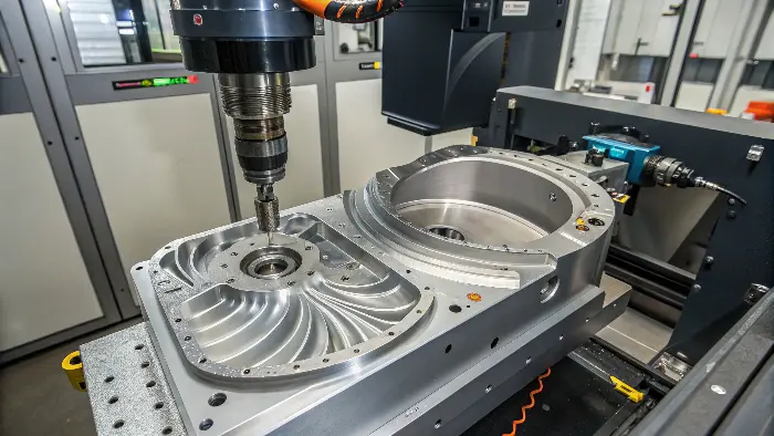
The "axis" count on a CNC machine simply refers to the number of directions it can move. The more axes, the more complex the parts it can create in a single operation. Understanding this is key to choosing the right machine for your job.
From Simple to Complex: The CNC Axis Breakdown
-
3-Axis CNC: This is the most common type of CNC machine. The cutting tool moves left-to-right (X-axis), front-to-back (Y-axis), and up-and-down (Z-axis). It’s great for parts with relatively simple geometry, like plates, brackets, and drilling features on a flat surface. However, to machine features on another side of the part, it must be manually unclamped, rotated, and re-clamped. This adds time and introduces potential for error.
-
4-Axis CNC: This adds one rotational axis to the mix, typically by allowing the workpiece itself to rotate. It’s excellent for making parts like camshafts or engraving text around a cylinder. It can do more than a 3-axis machine but still has limitations with highly complex, non-symmetrical shapes.
-
5-Axis CNC: This is the peak of machining capability. It combines the three linear axes with two rotational axes, allowing the tool to approach the workpiece from all sides. Think about machining an automotive impeller blade. Its surfaces are curved and twisted. A 5-axis machine can move its tool along these complex contours in one smooth, continuous motion. This not only produces a more accurate part but also provides a superior surface finish, which is critical for fluid dynamics and performance. It avoids multiple setups, which drastically improves accuracy, as the part is never moved from its initial position.
Here’s how they stack up for complex jobs:
| Feature | 3-Axis CNC | 5-Axis CNC |
|---|---|---|
| Part Complexity | Low to moderate | Very high |
| Handles Undercuts? | Poorly; requires multiple setups | Excellently; in a single setup |
| Surface Finish | Good on accessible surfaces | Superior, especially on curved surfaces |
| Setup Time | High (if multiple sides need work) | Low (often only one setup needed) |
| Programming Complexity | Simpler | More complex |
| Overall Cost | Lower machine and programming cost | Higher machine and programming cost |
For any project involving truly complex geometry in aluminum, 5-axis machining is not a luxury; it’s a necessity for achieving the required quality and efficiency.
Which machining process is best suited for creating cylindrical parts with high accuracy?
You have a critical cylindrical part, like a precise shaft or a custom pin. You need it to be perfectly round, with an excellent surface finish. Even a small deviation from perfect circularity could cause vibration, premature wear, or total failure in a high-performance automotive system.
CNC turning, also known as CNC lathing, is the specialized machining process designed specifically for creating cylindrical parts with exceptional accuracy. In CNC turning, the cylindrical workpiece is rotated at high speed while a stationary cutting tool removes material. This method ensures outstanding roundness, concentricity, and surface finish, making it the ideal choice.
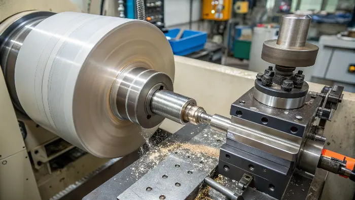
While CNC milling moves a rotating tool around a stationary part, CNC turning flips that concept. The part itself spins, and a non-rotating tool is fed into it. This fundamental difference is why turning is superior for creating any part that is primarily cylindrical.
The Power of CNC Turning
The main advantage of turning is its ability to produce features that are perfectly concentric with the part’s centerline. Since the part rotates and the tool moves in a straight line, the resulting cuts are naturally perfectly circular.
This process is used to create a wide variety of features on cylindrical parts:
- Diameters: Creating precise outer and inner diameters.
- Grooves: Cutting O-ring grooves or channels for snap rings.
- Threads: Machining external or internal threads for fasteners.
- Tapers: Creating conical shapes.
- Faces: Creating a perfectly flat face on the end of the shaft.
On a recent project, we were tasked with manufacturing a set of custom suspension pins for a race car team. The design required a roundness tolerance of less than 10 microns (0.010 mm). This level of precision is impossible to achieve reliably with molding or even standard milling. We used one of our high-precision CNC lathes to produce the pins. The result was a perfectly matched set that ensured the vehicle’s suspension geometry was exact, which is absolutely critical for high-speed handling and safety on the track.
Modern CNC turning centers can do even more. Many are equipped with "live tooling," which are small, powered milling or drilling tools mounted in the lathe’s turret. This creates a hybrid turn-mill machine that can perform secondary operations like milling a flat on a shaft, drilling an off-center hole, or cutting a keyway, all in the same single setup. This combines the precision of turning with the versatility of milling, allowing for the creation of incredibly complex cylindrical parts efficiently.
Can injection molding machines handle PEEK material efficiently?
You’ve identified PEEK as the perfect material for your component due to its amazing strength, light weight, and chemical resistance. But you’ve also heard whispers that it’s a very difficult and unforgiving material to work with. You can’t afford a process that results in weak parts or wasted material.
Yes, modern injection molding is a highly efficient method for producing PEEK parts in high volumes, but it is not a standard process. It demands specialized equipment, deep expertise, and very strict process control. The material’s high melting point and sensitivity to moisture mean you must partner with a manufacturer who is properly equipped and experienced with high-performance polymers.
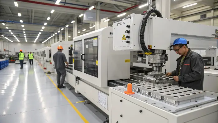
PEEK (Polyether Ether Ketone) is a true super-plastic, but its incredible properties come with unique manufacturing challenges. Simply putting PEEK pellets into a standard injection molding machine designed for ABS or Polypropylene will lead to disaster.
The Keys to Successfully Molding PEEK
Successfully molding PEEK comes down to managing three critical factors: temperature, moisture, and pressure.
-
Extreme Temperature Control: PEEK has a very high melting temperature, around 343°C (649°F). This requires a molding machine with a barrel and nozzle that can safely and consistently reach and maintain temperatures up to 400°C (752°F). Furthermore, the mold itself must be heated. To achieve the proper crystalline structure that gives PEEK its strength, the mold temperature must be held between 170°C and 200°C (340-390°F). This prevents the material from cooling too quickly, which would result in a brittle, amorphous part.
-
Moisture is the Enemy: PEEK is hygroscopic, meaning it absorbs moisture directly from the air. If these wet pellets are melted, the water turns to steam, creating bubbles, voids, and splay marks on the part’s surface. This not only looks bad but severely compromises the part’s structural integrity. To prevent this, PEEK pellets must be thoroughly dried in a special desiccant dryer for 3-4 hours at 150°C (300°F) immediately before they are fed into the molding machine.
-
Specialized Machine Components: Many grades of PEEK are filled with glass or carbon fibers to enhance their strength even further. These fillers make the molten plastic highly abrasive. Over time, this abrasive flow can wear out a standard machine’s steel screw and barrel. For this reason, machines dedicated to molding filled PEEK must be fitted with components made from specially hardened, wear-resistant alloys.
At CavityMold, we have invested heavily in the high-temperature machines, desiccant dryers, and expert knowledge required to process high-performance polymers like PEEK. Our engineers understand this isn’t just about melting plastic; it’s a science. We dial in the exact process parameters to ensure every PEEK part we produce meets the absolute highest standards of quality and performance.
Conclusion
Choosing between CNC machined aluminum and injection molded PEEK comes down to a clear assessment of your project’s needs. CNC aluminum offers unmatched precision and flexibility for prototypes and low-volume runs. Injection molded PEEK delivers cost-effective, complex, and high-strength parts for mass production.
